
Pipe winding mechanism for cement soil mixing pile machine

A technology for cement-soil mixing piles and pipelines, applied in the field of pipeline coiling mechanisms, can solve the problems of inability to drill a drill pipe, difficult drilling, long power transmission stroke, etc.

Pending Publication Date: 2018-11-13
周兆弟
View PDF2 Cites 0 Cited by
  • Summary
  • Abstract
  • Description
  • Claims
  • Application Information

AI Technical Summary

Problems solved by technology

[0004] The power control part of the aforementioned traditional cement-soil mixing pile driver is set on the upper part of the ground, and the power transmission stroke is long, which is prone to the problems that the drill pipe cannot be drilled, the drilling is difficult, and the stability is poor. Oil pipes and wires are also located on the ground. The applicant has applied for a more advanced chain drill bit with sufficient soil mixing, including a power system located at the lower part of the retractable drill pipe, which can enter the soil and water and can move along the circumferential direction. Turning end-to-end cutting carriers with raised structures on the surface

Method used


Image

  • Pipe winding mechanism for cement soil mixing pile machine
  • Pipe winding mechanism for cement soil mixing pile machine
  • Pipe winding mechanism for cement soil mixing pile machine

Examples


Embodiment Construction

[0024] The present invention will be further described in detail below in conjunction with the accompanying drawings and embodiments.

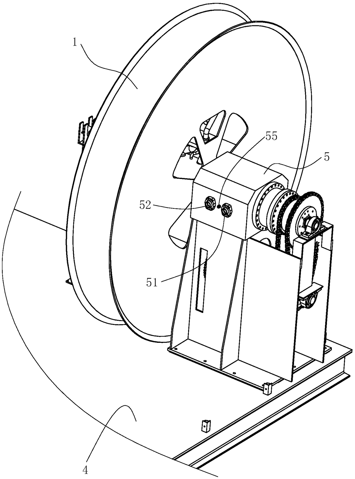
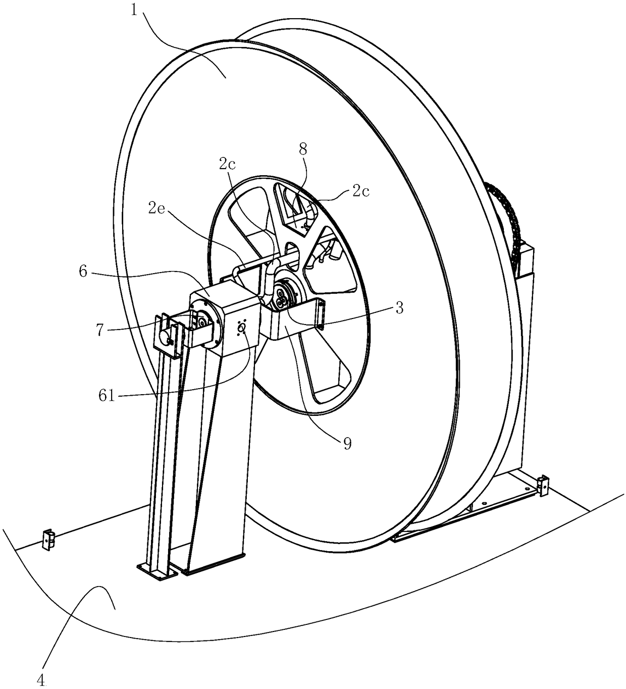
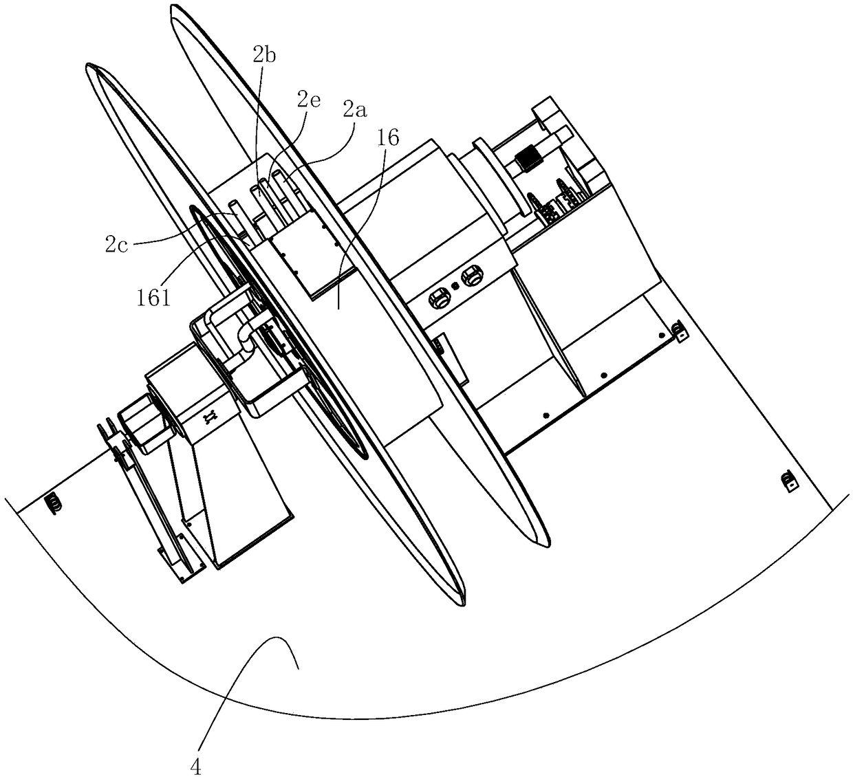
[0025] like Figure 1~6 Shown is a preferred embodiment of the present invention.

[0026] A pipeline coiling mechanism for a cement-soil mixing pile machine, characterized in that it includes

[0027]The wire reel 1, the inner hole of the wire reel 1 is pierced and fixed with a transmission shaft 3, and the wire reel 1 is fixed with an oil inlet pipe 2a and an oil outlet pipe that are always connected with the inner hole of the wire reel 1 2b and the oil discharge pipe 2d, the oil inlet pipe 2a, the oil outlet pipe 2b and the oil discharge pipe 2d all protrude from the coil wire peripheral surface of the coil coil drum 1.

[0028] The first support 5 is fixed on the cement-soil mixing pile machine platform 4. The transmission shaft 3 is passed through and supported in the first support 5 by bearings to rotate around its own axis. One end of...


PUM


Abstract

The invention relates to a pipe winding mechanism for a cement soil mixing pile machine. The pipe winding mechanism is characterized by comprising a winding reel, a transmission shaft, a first supportand a second support, wherein an oil inlet pipe and an oil outlet pipe are fixed to the winding reel and extend out from the winding circumferential surface of the winding reel; the transmission shaft is arranged in the first support in a penetration mode; the first support is provided with an oil inlet hole and an oil outlet hole; the transmission shaft is internally provided with an oil inlet channel and an oil outlet channel which are disconnected; the second support is provided with a slurry hole and is internally provided with a slurry shaft capable of rotating around the axis of the slurry shaft; the slurry shaft is internally provided with a slurry flow channel communicating with the slurry hole; a slurry pipe communicating with the slurry flow channel is fixed to the slurry shaft;and the other end of the slurry pipe extends out from the winding circumferential surface of the winding reel. Through the pipe winding mechanism, pipes can be normally wound around the winding reeland can also ensure that the pipes for delivering materials (slurry or mortar or oil) are not twined mutually without mutual interference.

Description

technical field [0001] The invention relates to a cement-soil mixing pile machine for pile foundation construction, in particular to a pipeline coiling mechanism for the cement-soil mixing pile machine. Background technique [0002] Cement-mixed pile foundation is an effective form of soft foundation treatment, especially in the reinforcement of weak soil layers and foundation pit support, the method of mixing cement slurry and soil is often used to form cement-soil mixed piles, so that the weak The strength and watertightness of the foundation have been greatly improved. It usually uses cement as the main agent of the curing agent, and uses the cement-soil mixing pile machine to spray the cement into the soil and mix the soft soil and the curing agent on the spot, so that a series of physical and chemical reactions between the cement and the soil occur, making it Condensate into a cement reinforcement with integrity, good water stability and high strength, and form a high-...

Claims


Application Information

Patent Timeline
IPC IPC(8): B65H75/38
CPCB65H75/38
Inventor 周兆弟
Owner 周兆弟
Learn More