Durable roller for spinning machine drafting mechanism

A durable, spinning machine technology, applied in the field of textile machinery, to achieve the effect of avoiding erosion, convenient and fast use, loading and unloading maintenance, and low maintenance cost

Inactive Publication Date: 2018-11-13
苏州益垚精密机械有限公司
View PDF0 Cites 0 Cited by
  • Summary
  • Abstract
  • Description
  • Claims
  • Application Information

AI Technical Summary

Problems solved by technology

The invention replaces the original hard connection between the shaft and the bearing by adding a rubber ring between the shaft and the inner sleeve of the bearing. Due to the elasticity of the rubber, the top roller can swing 360 degrees around the shaft, so the top roller can swing around the axis. 360-degree compensation avoids slipping, solves the problem of poor contact between the top roller and the roller, and greatly guarantees the quality of spinning; and it adopts a detachable combination design, the overall structure is simple, and can be It is directly installed on the pressure arm and used without fine-tuning, so it is convenient and quick to use, assemble, disassemble and maintain, with low maintenance cost in the later period, stable quality, strong implementability, and wide application range; it greatly improves the overall stability of the shaft through the protective layer. Weather resistance, so it has good high temperature resistance, wear resistance, acid and alkali resistance, and is durable; on the other hand, when unexpected situations such as fire occur, the staff can quickly cut off the main power supply through the emergency shutdown button, which greatly improves the safety. improve

Method used


Image

  • Durable roller for spinning machine drafting mechanism
  • Durable roller for spinning machine drafting mechanism

Examples


Embodiment 1

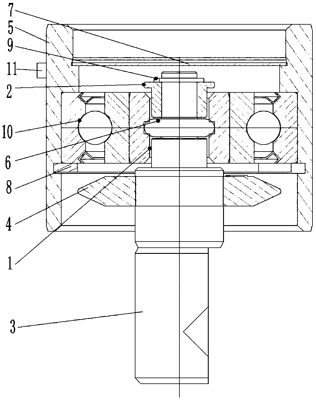
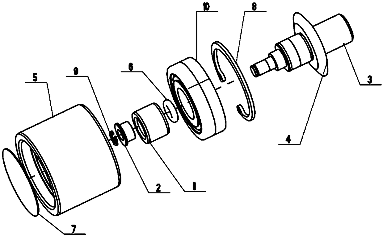
[0027] like Figure 1-Figure 2 As shown, a durable top roller used in the drafting mechanism of the spinning machine in this embodiment includes a bearing inner sleeve 1, a shaft sleeve 2, a shaft 3, a nylon ring 4, an outer sleeve 5, a rubber ring 6, a dust-proof Cover 7 , first retaining ring 8 , second retaining ring 9 , bearing 10 and emergency shutdown button 11 .

[0028] The connection relationship of the above components is as follows: the shaft 3 is connected to the bearing inner sleeve 1 and the shaft sleeve 2 in turn through the rubber ring 6, the end of the shaft 3 is sleeved with a second retaining ring 9, and the second washer 9 is in contact with the shaft sleeve 2; the middle part of the shaft 3 is sleeved with a nylon ring 4, and the lower part of the shaft sleeve 2 is sleeved inside the bearing inner sleeve 1; the bearing inner sleeve 1 is integrally sleeved inside the bearing 10, the The bearing 10 is embedded in the outer casing 5, and the two ends of the ...


PUM


Abstract

The invention discloses a durable roller for a spinning machine drafting mechanism, and mainly relates to the technical field of textile machinery. A nylon ring sleeves the middle of a shaft, and thelower portion of a shaft sleeve is sleeved with the inner side of a bearing inner sleeve; the bearing inner sleeve is integrally nested in a bearing, the bearing is nested in an outer sleeve, and thetwo ends of the bearing abut against the outer sleeve and a first check ring respectively; an emergency close button is arranged on one side of the outer sleeve; a protection layer is arranged on thesurface of the shaft and composed of an acid-base corrosion resistance layer, a high temperature resistance layer and a wear resistance layer; the acid-base corrosion resistance layer is a boron-containing phenol-formaldehyde-epoxy resin layer, the high temperature resistance layer is a polyurethane layer, and the wear resistance layer is a high manganese steel layer. The roller can perform enoughcompensation, the spinning quality is greatly guaranteed, the sealing property is good, the service life is long, the application range is wide, and the safety is good.

Description

technical field [0001] The invention relates to the technical field of textile machinery, in particular to a durable top roller used in a drafting mechanism of a spinning machine. Background technique [0002] Spinning machine is a kind of textile machinery that processes polyester, nylon and other pre-oriented yarns into different varieties and deniers through drafting and deformation. The drafting mechanism of the spinning machine must have sufficient holding force when drawing the tow. , so that the tow moves forward according to the surface speed of the roller to minimize the slippage of the tow in the drafting mechanism. The top roller is a part of the drafting mechanism, and its function is to press the tow on the roller to improve the holding force of the tow and reduce slippage. [0003] In recent years, with the continuous development of science and technology, related industries have higher and higher technical requirements for spinning machines. However, the exis...

Claims


Application Information

Patent Timeline
IPC IPC(8): D02J1/22
CPCD02J1/225D02J1/226
Inventor 张惠兴
Owner 苏州益垚精密机械有限公司
Why Eureka
Try Eureka