
Cooling device of compressor

A technology of cooling device and compressor, applied in the field of cooling device of compressor, can solve the problems of slow cooling speed, large floor space, poor effect, etc., and achieve the effect of saving water and energy

Inactive Publication Date: 2018-11-13
蚌埠市昊源压缩机制造有限公司
View PDF6 Cites 0 Cited by
  • Summary
  • Abstract
  • Description
  • Claims
  • Application Information

AI Technical Summary

Problems solved by technology

With the development of science and technology, the existing compressors often perform multi-stage compression on the gas, so as to effectively increase the pressure of the gas. After each stage of compression, it is usually necessary to cool down the compressed gas. The existing compressor cooling The device usually has two methods of water cooling and air cooling. The air cooling method has a slow cooling speed and poor effect, while the water cooling method occupies a large area and needs to be matched with a water cooling tower.

Method used


Image

  • Cooling device of compressor
  • Cooling device of compressor

Examples


Embodiment Construction

[0017] In order to make the object, technical solution and advantages of the present invention clearer, the present invention will be further described in detail below in conjunction with the accompanying drawings and embodiments. It should be understood that the specific embodiments described here are only used to explain the present invention, not to limit the present invention.

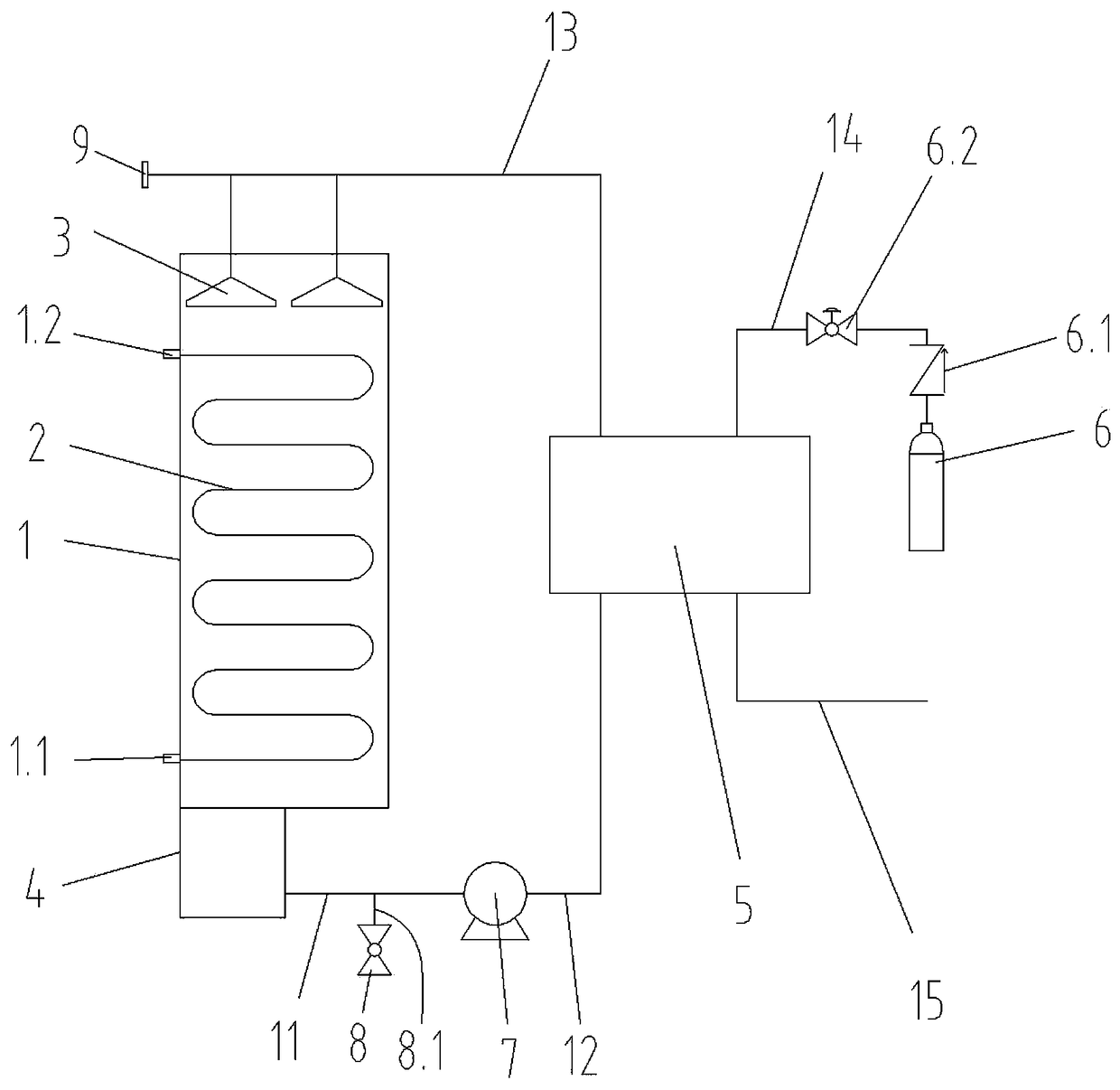
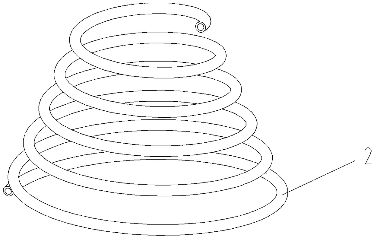
[0018] Such as Figure 1-Figure 2 As shown, a cooling device for a compressor provided by the present invention includes a cooling box 1, an air inlet joint 1.1 and an exhaust joint 1.2 are arranged on the cooling box 1, and a cooling pipe 2 is installed in the cooling box 1, and the cooling pipe 2 is in the form of The conical spiral is arranged in the cooling box 1, and the outer side of the cooling pipe 2 is evenly sleeved with a fin-shaped cooling ring. The number of turns of the cooling pipe 2 is five, and the diameter of the upper circle of the cooling pipe 2 increases successively from the ...


PUM


Abstract

The invention discloses a cooling device of a compressor. The cooling device comprises a cooling box, wherein a gas inlet joint and a gas outlet joint are arranged on the cooling box; a cooling tube is arranged in the cooling box; a group of spray heads is arranged above the cooling tube; the lower side of the cooling box is connected with a water collecting box in a matched mode; one side of thewater collecting box is equipped with a water drainage joint; the water drainage joint is connected with a liquid inlet interface of a water pump through a first pipeline; a liquid outlet interface ofthe water pump is connected with a cooling inlet of a cold-heat exchanger through a second pipeline; a cooling outlet of the cold-heat exchanger is connected to one end of a third pipeline; the otherend of the third pipeline is equipped with a blind plate; and each spray head communicates with the third pipeline through a connecting branch tube. The cooling device has the advantages that gas iscooled by cold water, half box of cold water is stored in the box, gas is cooled by the cold water in the cooling box after entering the cooling tube, cold water is sprayed to the cooling tube throughthe spray heads, and the cold water can be recycled through a cooling circulating machine, so that water energy is saved.

Description

technical field [0001] The invention relates to the field of industrial compressors, in particular to a compressor cooling device. Background technique [0002] A gas compressor is a power device that converts mechanical energy into gas pressure energy. It is often used to provide gas power for pneumatic tools. It is also commonly used for pressure delivery of oxygen, hydrogen, ammonia, natural gas, coke, etc. Furnace gas, inert gas and other media. With the development of science and technology, the existing compressors often perform multi-stage compression on the gas, so as to effectively increase the pressure of the gas. After each stage of compression, it is usually necessary to cool down the compressed gas. The existing compressor cooling The device usually has two methods of water cooling and air cooling. The air cooling method has a slow cooling speed and poor effect, while the water cooling method occupies a large area and needs to be equipped with a water cooling t...

Claims


Application Information

Patent Timeline
Patent Type & Authority Applications(China)
IPC IPC(8): F04B39/06
CPCF04B39/064
Inventor 乔兴军
Owner 蚌埠市昊源压缩机制造有限公司
Learn More