
Electric-hydraulic reversing valve

A hydraulic reversing valve and electric technology, which is applied in the field of hydraulic systems, can solve the problems of long judging time of the joystick, low work efficiency, and high labor intensity, and achieve the effects of reducing coaxiality, reducing labor intensity, and reducing labor intensity

Pending Publication Date: 2018-11-13
LIMING HYDRAULIC CO LTD
View PDF0 Cites 0 Cited by
  • Summary
  • Abstract
  • Description
  • Claims
  • Application Information

AI Technical Summary

Problems solved by technology

[0003] At present, the hydraulic reversing valves used in loaders are all manually driven to move the spool to achieve the purpose of reversing. This hydraulic reversing valve brings inconvenience to the work of the driver of the loader: when the driver works for a long time , physical and mental exhaustion is unavoidable. When shoveling, not only the judging time of the joystick is increased, the work efficiency is low, and it is inevitable that the loader will spend time doing useless work, wasting energy consumption, and when the driver manipulates the hydraulic valve, he needs to manually manipulate the joystick back and forth. labor intensive

Method used


Image

  • Electric-hydraulic reversing valve
  • Electric-hydraulic reversing valve
  • Electric-hydraulic reversing valve

Examples


Embodiment Construction

[0022] The following will clearly and completely describe the technical solutions in the embodiments of the present invention with reference to the accompanying drawings in the embodiments of the present invention. Obviously, the described embodiments are only some, not all, embodiments of the present invention. Based on the embodiments of the present invention, all other embodiments obtained by persons of ordinary skill in the art without making creative efforts belong to the protection scope of the present invention.

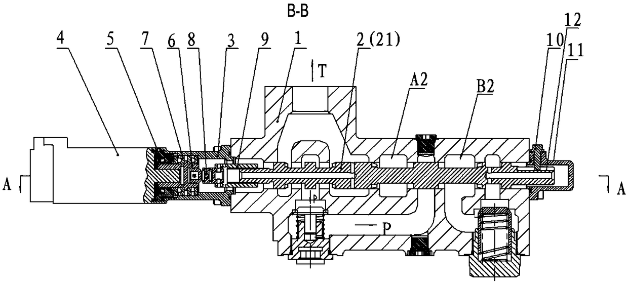
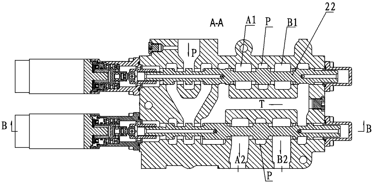
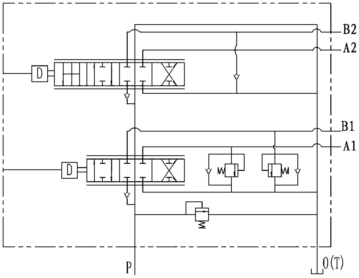
[0023] refer to Figure 1-3 , an electro-hydraulic reversing valve, using a servo motor 4 to control the direction and flow of the hydraulic reversing valve, including: a servo motor 4, a motor bushing 6, a plane bearing 7, a miniature universal joint 8, a multi-head nut 9, and a valve body 1 and the spool 2, the spool 2 is rotated by the servo motor 4 to make a linear sliding motion in the valve hole inside the valve body 1; the motor seat 3 is fixed on the v...


PUM


Abstract

The invention discloses an electric-hydraulic reversing valve. The electric-hydraulic reversing valve comprises a valve body, a valve element, a servo motor and a transmission mechanism. The valve element slides in a valve hole in the valve body. A motor seat is fixedly arranged on the valve body. A servo motor is fixed to the motor seat. One end of the motor seat is provided with a plug. The output end of the servo motor is connected with a motor shaft sleeve, and the other end of the motor shaft sleeve is linked with a minisize cardan joint. A plane bearing is assembled on the motor shaft sleeve. One end of the minisize cardan joint is connected with a multi-head nut. The multi-head nut is in multi-head threaded connection with one end of the valve element, and the other end of the valveelement is provided with a valve element anti-rotation device. According to the electric-hydraulic reversing valve, the valve element is controlled by the servo motor to perform linear motion, and position control is conducted precisely and in time; by means of a computer control unit, digital signal control over the electric-hydraulic reversing valve is achieved, and automation, informatizationand intelligentization of complex operation are achieved; and on one hand, labor intensity of operators is lowered, operation skills of the operators are improved, and on the other hand, the purposesof energy conservation and consumption reduction are achieved.

Description

technical field [0001] The invention relates to the technical field of hydraulic systems, and more specifically relates to an electro-hydraulic reversing valve. Background technique [0002] The hydraulic reversing valve is the key core component of the loader's working hydraulic system. It controls the direction and flow of the loader's shoveling, lifting, unloading, lowering, and leveling of the bucket during the working process of the loader. [0003] At present, the hydraulic reversing valves used in loaders are all manually driven to move the spool to achieve the purpose of reversing. This hydraulic reversing valve brings inconvenience to the work of the driver of the loader: when the driver works for a long time , physical and mental exhaustion is unavoidable. When shoveling, not only the judging time of the joystick is increased, the work efficiency is low, and it is inevitable that the loader will spend time doing useless work, wasting energy consumption, and when th...

Claims


Application Information

Patent Timeline
Patent Type & Authority Applications(China)
IPC IPC(8): F15B13/02
CPCF15B13/02
Inventor 梁富春叶萍罗国光
Owner LIMING HYDRAULIC CO LTD
Learn More