Dynamic load bearing design method applied to reciprocating compressor crankshaft

A technology of compressor crankshaft and design method, which is applied to crankshaft bearings, design optimization/simulation, special data processing applications, etc., can solve problems such as failure to meet bearing safety requirements, and achieve the effect of high safety

Active Publication Date: 2018-11-13
XI AN JIAOTONG UNIV
View PDF3 Cites 12 Cited by
  • Summary
  • Abstract
  • Description
  • Claims
  • Application Information

AI Technical Summary

Problems solved by technology

Initially, the design parameters of the dynamic load bearing were based on the minimum oil film thickness. With the development of technology, subsequent designs also required the calculation of the maximum oil film pressure and temperature. However, due to the complexity of the dynamic load bearing working conditions, this calculation still cannot satisfy Bearing Safety Requirements

Method used


Image

  • Dynamic load bearing design method applied to reciprocating compressor crankshaft
  • Dynamic load bearing design method applied to reciprocating compressor crankshaft
  • Dynamic load bearing design method applied to reciprocating compressor crankshaft

Examples


Embodiment Construction

[0074] The present invention is described in further detail below in conjunction with accompanying drawing:

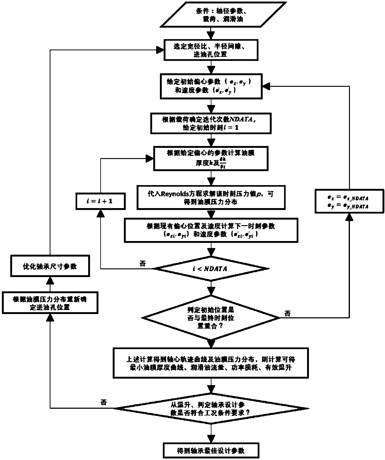
[0075] like figure 1 As shown, it is a dynamic load bearing design process. A dynamic load bearing design method applied to the crankshaft of a reciprocating compressor provided by the present invention includes the following steps:

[0076] 1. Determine the width-to-diameter ratio B / D according to the working conditions of the bearing (where B is the bearing width and D is the bearing diameter). For dynamic bearings, it is preferably 0.3 to 0.8. For bearings with complete circumferential grooves, it is usually preferred to choose the preferred range The upper limit (B / D=0.8), and the lower limit (B / D=0.3) for bearings without circumferential grooves and oil inlet holes;

[0077] 2. Refer to the diameter of the journal to determine the minimum radial clearance of the bearing, and the maximum value of the radial clearance of the bearing is 1.5 times the minimum value: ...


PUM


Abstract

The invention discloses a dynamic load bearing design method applied to a reciprocating compressor crankshaft. The method solves the problems that in the traditional dynamic load bearing design process, parameters are difficult to determine, and characteristic parameter calculation is complex. The design method comprises the steps of width-diameter ratio design and radius gap interval computationin the bearing design process, and further comprises the step of calculation of pressure distribution, minimum oil film thickness, oil film pressure, lubricating oil flow, power loses, equivalent temperature rise and the like of a bearing, all parameter indexes of the bearing are checked more comprehensively, and the design objective safety is high. According to the method, a finite element methodis adopted for solving a Reynolds equation, compared with traditional experience formula computing, more parameters can be obtained, as for the bearing, with the complex variable working condition, like the dynamic load bearing, the design steps are simplified, and the design time is saved; and design of a bearing oil inlet hole is carried out by drawing a cloud picture of a pressure crankshaft angle and a bearing circumferential unfolding angle.

Description

technical field [0001] The invention belongs to the field of bearing design, and in particular relates to a design method of a dynamic bearing applied to a crankshaft of a reciprocating compressor. Background technique [0002] In reciprocating compressors, the load acting on the sliding bearings, regardless of magnitude and direction, changes periodically with time, and such bearings are generally called dynamic bearings. Since the load changes, the equilibrium position of each instantaneous axis also changes. [0003] The crankshaft in the reciprocating compressor rotates at a constant angular velocity under the action of the flywheel and the governor, and the connecting rod oscillates at a varying angular velocity relative to the crankshaft and the piston. Because the reciprocating inertial force generated by the moving parts of the reciprocating compressor is difficult to balance, only a low speed can be used to suppress vibration, and the load on the bearing is relativ...

Claims


Application Information

Patent Timeline
Patent Type & Authority Applications(China)
IPC IPC(8): F16C9/02G06F17/50
CPCF16C9/02G06F30/17G06F30/23
Inventor 裴世源洪军郑文斌王文超
Owner XI AN JIAOTONG UNIV
Why Eureka
Try Eureka