Air source heat pump floor heating system

An air source heat pump and heating system technology, applied in the field of heating systems, can solve problems such as insufficient heating capacity, achieve reasonable water flow direction, increase heating effect and working effect, and solve the effect of insufficient heating capacity

Inactive Publication Date: 2018-11-13
海宁梅尔环境科技有限公司
View PDF5 Cites 0 Cited by
  • Summary
  • Abstract
  • Description
  • Claims
  • Application Information

AI Technical Summary

Problems solved by technology

[0004] The main purpose of the present invention is to provide an air source heat pump floor heating system, through the porous solid surface of the activated carbon plate, absorb and remove the organic matter or impurities in the water, through the auxiliary electric heater, effectively solve the problem of insufficient heating in winter, and Through the water separator and the water collector, the direction of the water flow is reasonable and the thermal efficiency is improved, which can effectively solve the problems in the background technology

Method used


Image

  • Air source heat pump floor heating system
  • Air source heat pump floor heating system

Examples


Embodiment Construction

[0019] In order to make the technical means, creative features, objectives and effects of the present invention easy to understand, the present invention will be further explained below in conjunction with specific embodiments.

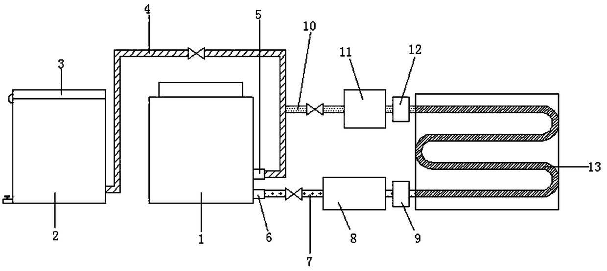
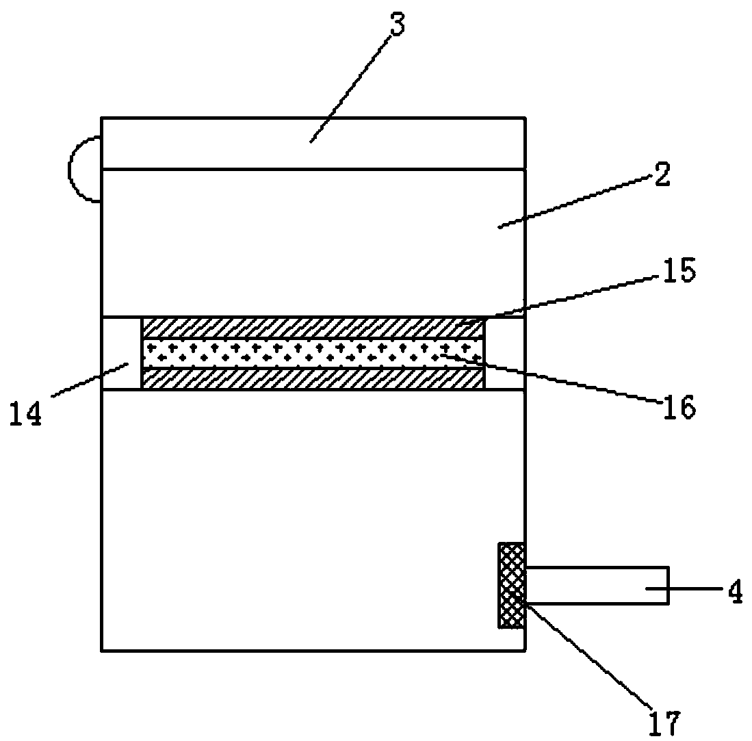
[0020] Such as Figure 1-2 As shown, an air source heat pump floor heating system includes an air energy heat pump unit 1 and a heat preservation water tank 2. The air heat pump unit 1 is provided with a heat preservation water tank 2 on one side, and the bottom of the heat preservation water tank 2 is detachably connected to a number one pipe 4. The bottom of the air energy heat pump unit 1 is provided with a cold water inlet 5, one side of the cold water inlet 5 is provided with a hot water outlet 6, and the other side of the air energy heat pump unit 1 is provided with a second pipe 7. An auxiliary electric heater 8 is detachably connected to one end of the No. 1 pipe 7, a return pipe 10 is fixedly connected to the surface of the No. 1 pipe 4, a circu...


PUM


Abstract

The invention discloses an air source heat pump floor heating system which comprises an air energy heat pump unit and a heat preservation water tank. The heat preservation water tank is arranged on one side of the air energy heat pump unit, a cold water inlet is formed in the bottom of the air energy heat pump unit, one side of the cold water inlet is provided with a hot water outlet, and the other side of the air energy heat pump unit is provided with a second pipeline. One end of the second pipeline is detachably connected with an auxiliary electric heater, the surface of the first pipelineis fixedly connected with a water return pipe, and one end of the water return pipe is detachably connected with a circulating pump. A sponge plate is detachably connected to the upper surface of a boss, and an activated carbon plate is arranged in an inner cavity of the sponge plate. Organic matters or impurities in water are adsorbed and removed through the porous solid surface of the activatedcarbon plate, and through the auxiliary electric heater, the problem that the heating amount in winter is insufficient is effectively solved; and the water flow direction is reasonable through a waterdistributor and a water collector, so that the heat efficiency is improved.

Description

Technical field [0001] The invention relates to a heating system, in particular to an air source heat pump floor heating system. Background technique [0002] The working principle of the floor heating system is to use the circulating hot water in the closed pipeline laid under the floor to gently dissipate heat in the entire room. The circulating hot water required in the system can be heated by any energy source, such as a traditional gas boiler , Heat pump units can also use renewable energy sources, such as ground source heat pumps and solar energy. [0003] The prior art air source heat pump floor heating system cannot filter the water body, resulting in the air-energy heat pump unit remaining in the water after long-term operation, affecting the service life. In northern my country where the outdoor air temperature is low, the heat pump provides heating in winter Insufficient quantity affects normal heating, the design of water flow direction is unreasonable, and the thermal ...

Claims


Application Information

Patent Timeline
Patent Type & Authority Applications(China)
IPC IPC(8): F24D3/10F24D3/12F24D3/18F24D19/00
CPCF24D3/1066F24D3/12F24D3/18F24D19/0092F24D2200/32F24D2220/0207
Inventor 郭宗俊
Owner 海宁梅尔环境科技有限公司
Why Eureka
Try Eureka