
A Measuring Method of Catenary Geometric Parameters Based on Geometric Magnification Principle and Monocular Computer Vision

A technology of computer vision and geometric parameters, which is applied to measuring devices, instruments, and optical devices, etc., can solve the problems of complex process of contact wire lead height and pull-out value, inability to meet high-precision real-time measurement, and involving many parameters, etc. Achieve the effects of good real-time measurement, high cost performance and low computing resource requirements

Active Publication Date: 2020-01-10
BEIJING JIAOTONG UNIV
View PDF5 Cites 0 Cited by
  • Summary
  • Abstract
  • Description
  • Claims
  • Application Information

AI Technical Summary

Problems solved by technology

[0009] Existing methods cannot identify the laser spot from the image stably, efficiently, and accurately. The process of calculating the conductance and pull-out value of the contact line from the coordinates of the image spot is complex, involving many parameters, large errors, and long delays. Can not meet the requirements of high-precision real-time measurement

Method used

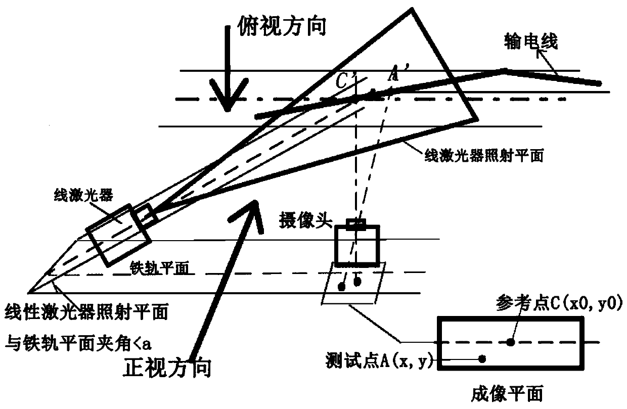
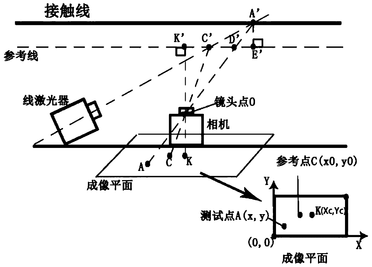

Image

  • A Measuring Method of Catenary Geometric Parameters Based on Geometric Magnification Principle and Monocular Computer Vision
  • A Measuring Method of Catenary Geometric Parameters Based on Geometric Magnification Principle and Monocular Computer Vision
  • A Measuring Method of Catenary Geometric Parameters Based on Geometric Magnification Principle and Monocular Computer Vision

Examples


Embodiment Construction

[0061] In order to illustrate the present invention more clearly, the present invention will be further described below in conjunction with preferred embodiments and accompanying drawings. Similar parts in the figures are denoted by the same reference numerals. Those skilled in the art should understand that the content specifically described below is illustrative rather than restrictive, and should not limit the protection scope of the present invention.

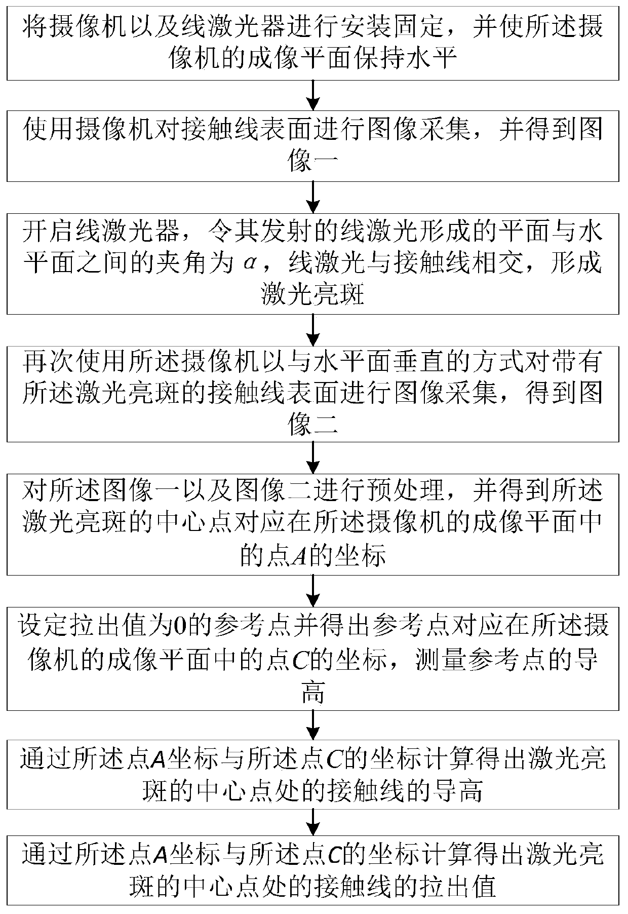
[0062] Such as figure 1 Shown, a kind of catenary geometric parameter measurement method based on geometric magnification principle and monocular computer vision, the method comprises the following steps:

[0063] Install and fix the camera and line laser, and keep the imaging plane of the camera horizontal;

[0064] Use a camera to collect images on the surface of the contact line, and obtain image 1;

[0065] Turn on the line laser so that the angle between the plane formed by the emitted line laser and the horizontal ...


PUM


Abstract

The invention discloses a catenary geometric parameter measuring method based on geometric amplification principle and monocular computer vision. The method comprises the steps of retaining the imaging plane of a camera to be horizontal; using the camera to carry out image acquisition on a contact line and obtain a first image; turning on a linear laser, enabling the included angle between the plane formed by the linear laser emitted by the linear laser and the horizontal plane is alpha, line laser intersecting with the contact line to form a laser bright spot; using the camera to carry out image acquisition on the contact line with the laser bright spot to obtain a second image; carrying out preprocessing on the first image and the second image, and obtaining the coordinate of a point Acorresponding to the center point A 'of the laser bright spot in the imaging plane of the camera, setting C' and obtaining the coordinates of the point C of the C 'in the imaging plane, measuring theguide height of the C ', and calculating the guide height and the pull-out value of the contact line at the A ' according to the coordinates of the point A and the point C. According to the invention,high-precision real-time measurement can be carried out on the guide height and the pull-out value of a contact line.

Description

technical field [0001] The invention relates to the technical field of electrified railway power supply, in particular to a catenary geometric parameter measurement method based on the geometric magnification principle and monocular computer vision. Background technique [0002] In the electrified railway power supply system, the catenary is the transmission circuit erected along the railway line to supply power to the electric locomotive, and the catenary wire is the wire that supplies power to the electric locomotive. In order to ensure a good contact between the contact wire and the pantograph of the electric locomotive, the geometric parameters of the contact wire must be set accurately, and the most important parameters include the conductivity and pull-out value of the contact wire. The guide height of the contact line is the vertical height from the contact line to the rail plane, and the pull-out value is the horizontal offset distance of the contact line at the posi...

Claims


Application Information

Patent Timeline
Patent Type & Authority Patents(China)
IPC IPC(8): G01B11/02G01B11/14
CPCG01B11/02G01B11/14
Inventor 彭亚辉姜旺俊朱中杰杨浩雷曹旭阳陈后金
Owner BEIJING JIAOTONG UNIV
Learn More