
Device for quantitatively evaluating image quality of photoelectric imaging system under boundary temperature condition

A technology of photoelectric imaging and boundary temperature, applied in the field of optical detection, can solve the problems that have not been seen in relevant reports, restrict the performance evaluation of photoelectric imaging systems, transfer functions, and resolution cannot be assessed, etc.

Pending Publication Date: 2018-11-13
中国人民解放军陆军沈阳军事代表局驻长春地区军事代表室
View PDF0 Cites 2 Cited by
  • Summary
  • Abstract
  • Description
  • Claims
  • Application Information

AI Technical Summary

Problems solved by technology

However, due to the limitation of test conditions, the current domestic photoelectric imaging system can only perform image quality evaluation in conventional temperature environment and storage test in high and low temperature environment. However, the key indicators of the imaging quality that determine the performance of the optoelectronic imaging system, such as transfer function and resolution, cannot be assessed under boundary temperature conditions.
The limitation of test conditions and methods restricts the performance evaluation of the photoelectric imaging system, laying hidden dangers for its application and performance in the boundary temperature environment
[0004] So far, there have been no relevant reports on this kind of boundary temperature condition photoelectric imaging system image quality quantitative evaluation device

Method used


Image

  • Device for quantitatively evaluating image quality of photoelectric imaging system under boundary temperature condition
  • Device for quantitatively evaluating image quality of photoelectric imaging system under boundary temperature condition
  • Device for quantitatively evaluating image quality of photoelectric imaging system under boundary temperature condition

Examples


Embodiment Construction

[0017] The present invention will be described in further detail below in conjunction with the accompanying drawings.

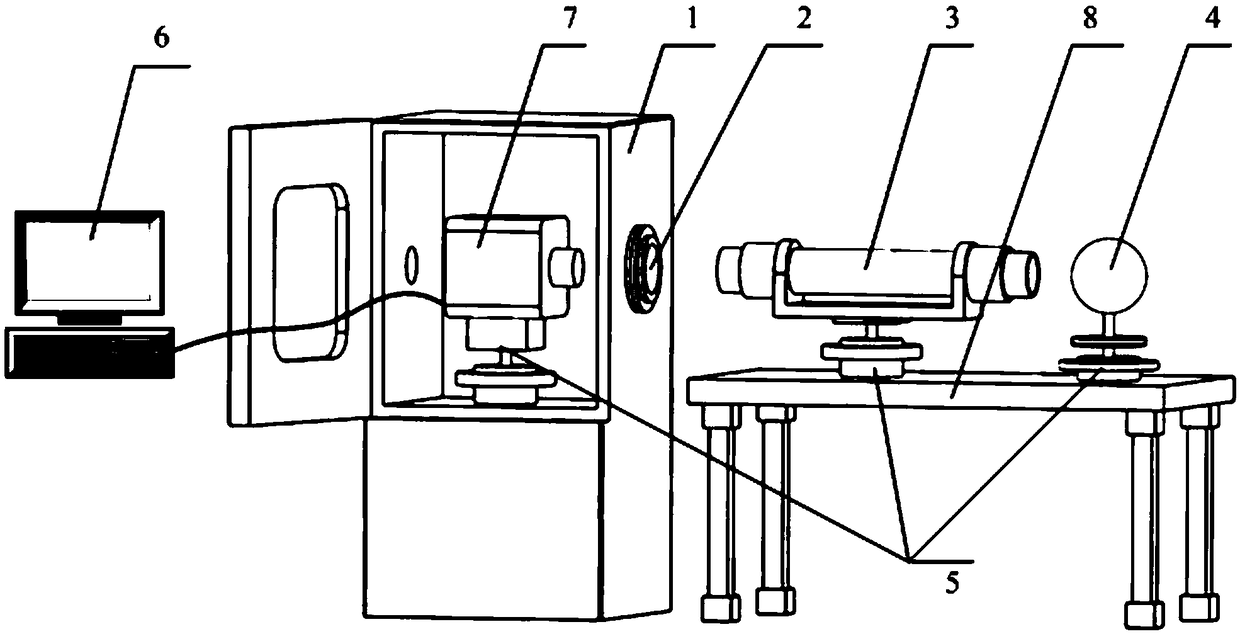
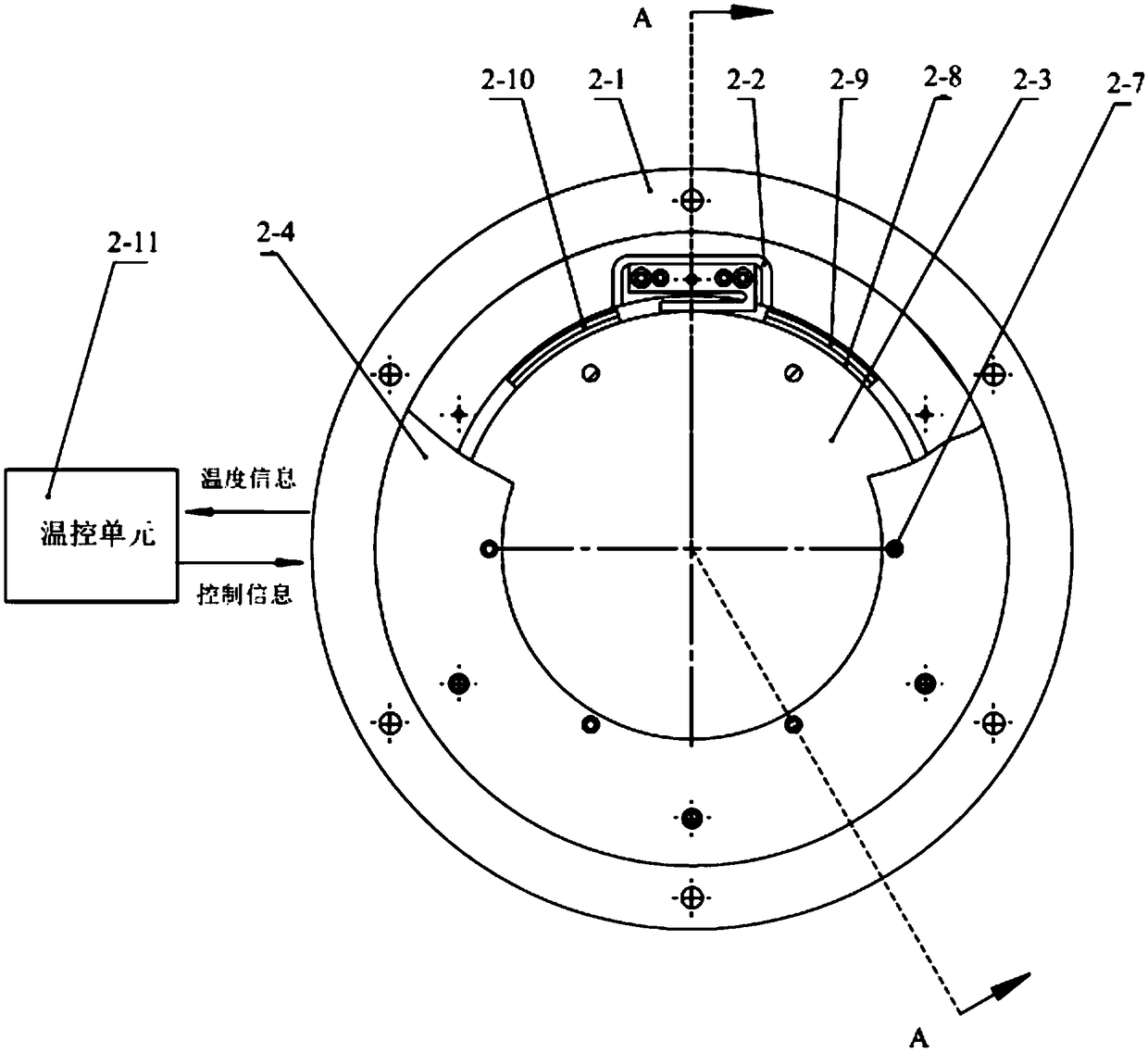
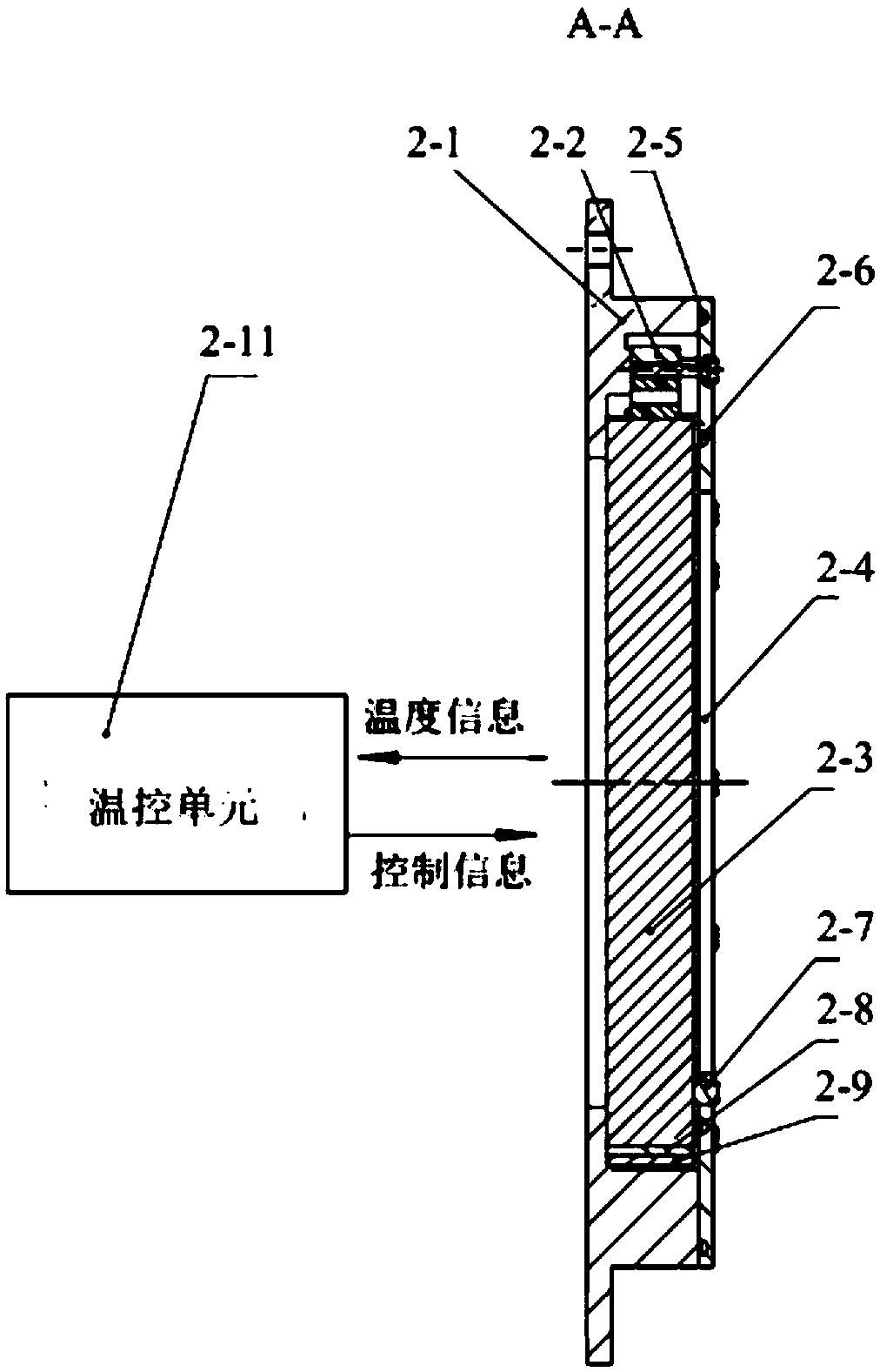
[0018] Such as figure 1 As shown, the image quality quantitative evaluation device of the photoelectric imaging system under boundary temperature conditions mainly includes a temperature simulation device 1, an optical window 2, a collimator 3, an integrating sphere 4, three mechanical adjustment devices 5, a computer processing system 6 and a test bench 8 . Wherein, the temperature simulation device 1 is a high and low temperature test chamber with a dehumidification function, which is used to simulate the temperature environment of the photoelectric imaging system 7 under test; the optical window 2 is fixed on the through hole position of the side wall of the temperature simulation device 1 by bolts The photoelectric imaging system 7 under test, the optical window 2, the collimator 3 and the integrating sphere 4 are coaxially arranged in sequence; the coll...


PUM


Abstract

The invention relates to a device for quantitatively evaluating the image quality of a photoelectric imaging system under a boundary temperature condition and belongs to the optical detection field. In order to meet the needs of the prior art, the device mainly comprises a temperature simulation device, an optical window, a collimator, an integrating sphere, three mechanical adjustment devices, acomputer processing system and a test bench; the temperature simulation device is a high- and low-temperature test chamber with a dehumidification function; a photoelectric imaging system under test is arranged in the temperature simulator; the optical window is fixed at a through hole in the side wall of the temperature simulation device; the photoelectric imaging system under test, the optical window, the collimator and the integrating sphere are arranged coaxially in sequence; the photometric imaging system under test, the collimator and the integrating sphere are respectively arranged on the three mechanical adjustment devices; the mechanical adjustment devices where the collimator and the integrating sphere are located are mounted on the test bench; and the computer processing systemis connected with the photoelectric imaging system under test. With the device adopted, the image quality of a typical photoelectric imaging system can be quantitatively evaluated under the boundary temperature condition.

Description

technical field [0001] The invention relates to an image quality quantitative evaluation device of a photoelectric imaging system under boundary temperature conditions, which belongs to the field of optical detection and is mainly used for realizing image quality testing and quantitative evaluation of a typical photoelectric imaging system under boundary temperature conditions. Background technique [0002] Image quality is one of the key performance indicators of optoelectronic imaging systems, and it is a key concern in the field of optical inspection, which directly affects the design, manufacture and use of optoelectronic imaging systems. Studies have shown that temperature has a direct impact on the image quality of optoelectronic imaging systems. [0003] With the rapid development of photoelectric technology and image processing technology, photoelectric imaging systems are more and more widely used in detection, aiming, calibration and detection. Depending on the ap...

Claims


Application Information

Patent Timeline
IPC IPC(8): G01M11/00
CPCG01M11/00
Inventor 赵贵军张磊张松王海伟张崇崔超孙树红权明吉彭佳琦张继真
Owner 中国人民解放军陆军沈阳军事代表局驻长春地区军事代表室
Learn More