
Track-type vehicle aiming mirror detection device

A technology for detection devices and sights, which is applied in measuring devices, vehicle tests, optical instrument tests, etc., can solve problems such as reduced equipment usage, low equipment maintenance efficiency, and equipment cycle growth, and achieves improved use efficiency and versatility Good, light weight effect

Pending Publication Date: 2018-11-13
ARMY ENG UNIV OF PLA
View PDF4 Cites 2 Cited by
  • Summary
  • Abstract
  • Description
  • Claims
  • Application Information

AI Technical Summary

Problems solved by technology

The most important part of the maintenance work of tracked vehicle sights is to perform performance testing, maintenance and troubleshooting. However, at present, the detection of tracked vehicle sights is mainly carried out manually, usually by maintenance personnel. Based on experience in fault diagnosis or replacement of parts one by one, the operation is cumbersome and the accuracy is poor, and often requires multiple replacements to locate the fault and fill in the fault damage of the parts
The maintenance efficiency of such equipment is low, which leads to an increase in the maintenance cycle of equipment and reduces the utilization rate of equipment.

Method used


Image

  • Track-type vehicle aiming mirror detection device
  • Track-type vehicle aiming mirror detection device
  • Track-type vehicle aiming mirror detection device

Examples


Embodiment Construction

[0028] In order to have a clearer understanding of the technical features, purposes and effects of the present invention, the specific implementation manners of the present invention will now be described in detail with reference to the accompanying drawings.

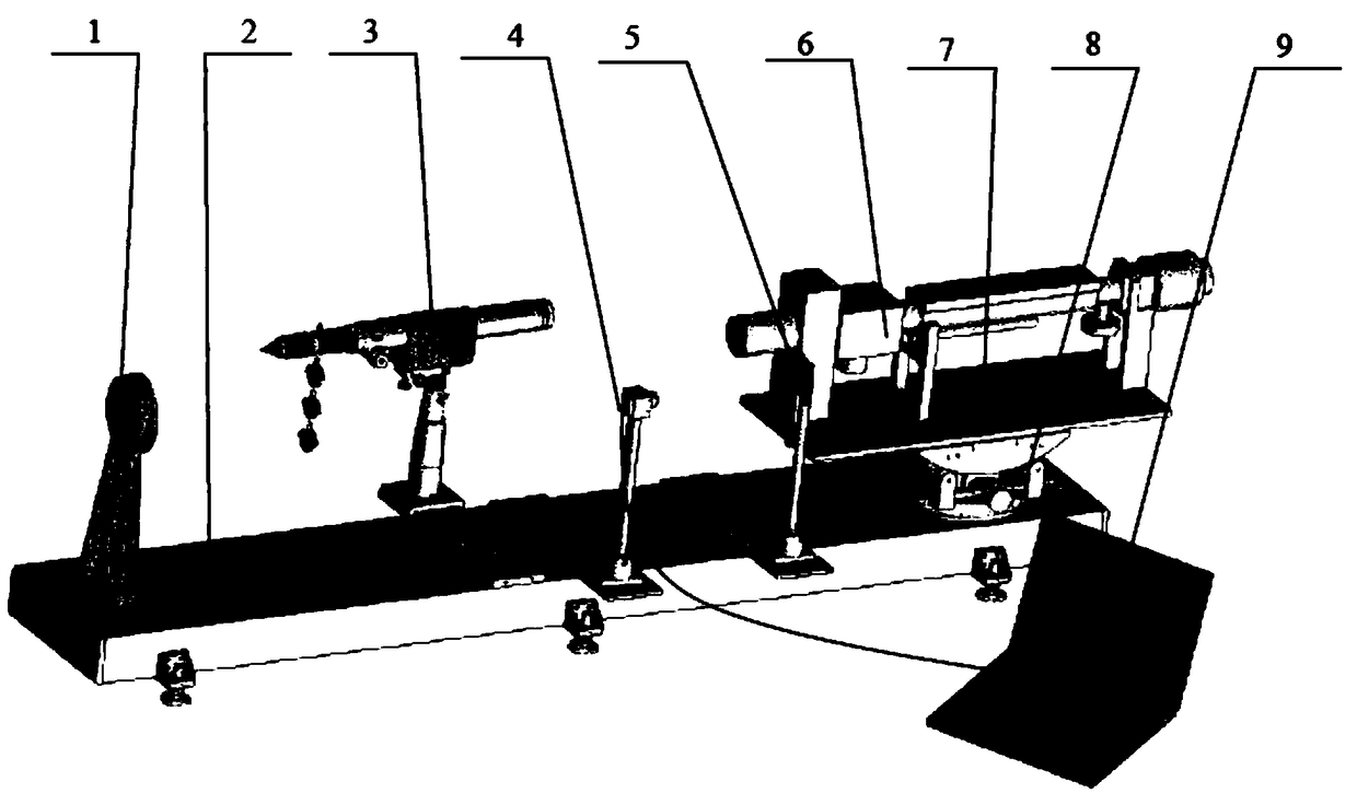
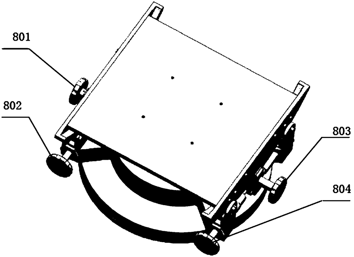
[0029] Such as Figure 1-3 As shown, the tracked vehicle sight detection device of the present invention includes a base 2, on which a spherical reflector 1, an adjustable collimator 3, a CCD assembly 4, a target assembly 5 and a cradle seat are sequentially arranged from left to right 8.

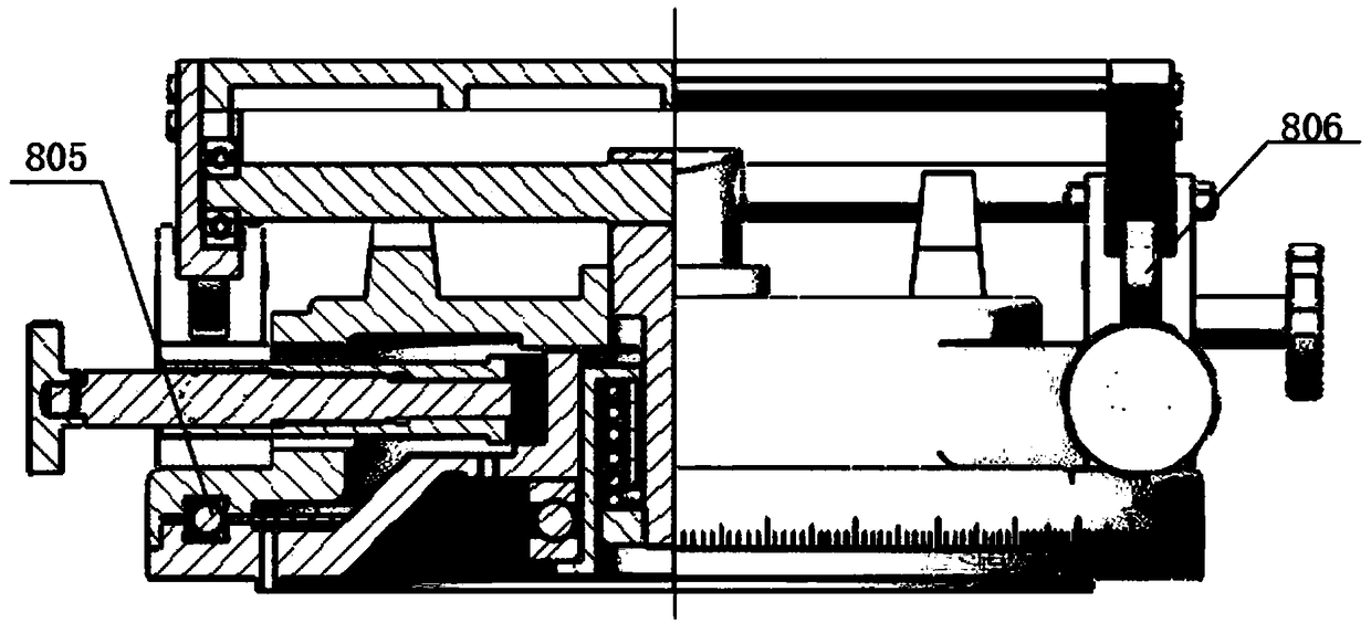
[0030] The CCD assembly 4 is connected to the computer 9, and the cradle seat 8 is fixed with a bracket 7 for installing the product 6 to be tested. The cradle seat 8 comprises a fixed seat and a rotating seat, and the support 7 is fixed on the rotating platform. The rotating seat and the fixed seat are connected through a pitch bearing 806, and the cradle seat 8 also includes a pitch adjustment mechanism. The pitch adjustment mec...


PUM


Abstract

The invention relates to a track-type vehicle aiming mirror detection device which comprises a base. A spherical emitting mirror, an adjustable collimator, a CCD component, a target component and a rocking basket seat are sequentially arranged on the base from left to right, the CCD component is connected with a computer, a support for mounting a to-be-detected product is arranged on the rocking basket seat, the rocking basket seat comprises a fixed seat and a rotating seat which are connected through a pitching bearing and further comprises a pitching adjusting mechanism and a direction adjusting mechanism, and the rotating seat and the fixed seat can be in rotatable connection through a steel ball and a rail. The device can detect and correct indexes like resolution, optical parallax andoptical axis parallelism of a track-type vehicle aiming mirror to ensure the same to be capable of accurately aiming and measuring a target. The device can be used for detecting laser spot size of alaser device.

Description

technical field [0001] The invention relates to a sight detecting device, more specifically, relates to a crawler vehicle sight detecting device. Background technique [0002] The scope of the tracked vehicle is mainly used to complete the observation, search, aiming, tracking and ranging of the target. The most important part of the maintenance work of tracked vehicle sights is to perform performance testing, maintenance and troubleshooting. However, at present, the detection of tracked vehicle sights is mainly carried out manually, usually by maintenance personnel. It is cumbersome to operate and the accuracy is poor, and it often needs multiple replacements to locate the fault and fill in the fault damage of the parts. The maintenance efficiency of such equipment is low, which leads to an increase in the maintenance cycle of the equipment and reduces the utilization rate of the equipment. Contents of the invention [0003] The technical problem to be solved by the pre...

Claims


Application Information

Patent Timeline
Patent Type & Authority Applications(China)
IPC IPC(8): G01M17/007G01M11/02
CPCG01M11/0207G01M11/0214G01M17/007
Inventor 程治新黄林昊张瑞杨云飞龚长红全振中邹先国廖学兵吴建磊明骁文谷生
Owner ARMY ENG UNIV OF PLA
Learn More