Optical fiber scanner connecting structure

A connection structure and optical fiber scanning technology, which is applied in optics, instruments, optical components, etc., can solve the problems of loss, scanning displacement cannot fully and effectively transmit optical fibers, and increase the power consumption of single-fiber resonance piezoelectric scanners.

Active Publication Date: 2018-11-13
CHENGDU IDEALSEE TECH
View PDF13 Cites 2 Cited by
  • Summary
  • Abstract
  • Description
  • Claims
  • Application Information

AI Technical Summary

Problems solved by technology

[0006] When the piezoelectric element is bent and deformed, it is necessary to transmit the force of the piezoelectric element to the optical fiber through the connecting part, so that the scanning displacement formed by the vibration of the piezoel...

Method used


Image

  • Optical fiber scanner connecting structure
  • Optical fiber scanner connecting structure
  • Optical fiber scanner connecting structure

Examples


Embodiment Construction

[0051] The following will clearly and completely describe the technical solutions in the embodiments of the present invention with reference to the accompanying drawings in the embodiments of the present invention. Obviously, the described embodiments are only some, not all, embodiments of the present invention. Based on the embodiments of the present invention, all other embodiments obtained by persons of ordinary skill in the art without creative efforts fall within the protection scope of the present invention.

[0052] An embodiment of the present invention provides a connection structure of an optical fiber scanner, which is used to effectively transmit the driving force of the piezoelectric element to the optical fiber without attenuation.

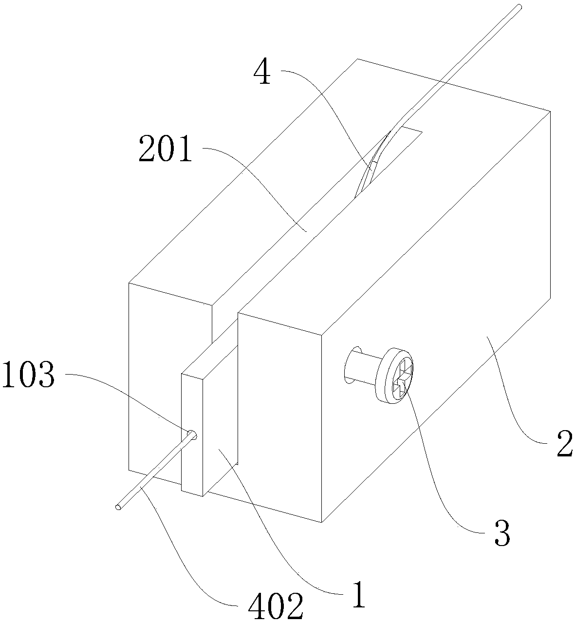
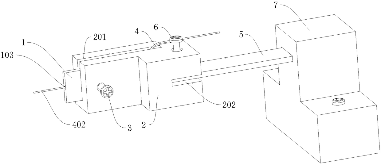
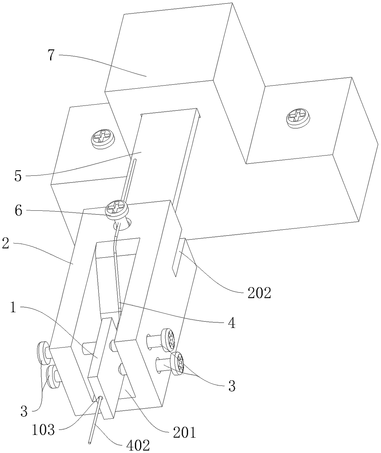
[0053] A fiber scanner connection structure provided by an embodiment of the present invention, such as figure 1 shown, including:

[0054] A first scan driver 1, which has a fixed end and a free end;

[0055] The connecting seat 2...


PUM


Abstract

The invention discloses an optical fiber scanner connecting structure. The optical fiber scanner connecting structure comprises a first scanning driver provided with a fixed end and a free end; a connecting base provided with a first groove body, in which the fixed end of the first scanning driver is arranged; and at least one first pressing piece arranged on the side wall of the first groove body, wherein the tail end of the first pressing piece extends into the first groove body and presses the fixed end of the first scanning driver. The scanning beam emitting end of an optical fiber performs one-dimensional vibration or two-dimensional vibration under the driving of the first scanning driver. The scanning driver is tightly pressed in the groove body through the pressing piece, and the scanner is fixed. The optical fiber is fixedly arranged on the first scanning driver. The use of the connecting part is avoided, the loss of the force due to the connecting part is avoided. The drivingforce of the first scanning driver can be effectively transmitted to the optical fiber without being attenuated, and therefore the vibration amplitude of the optical fiber is increased.

Description

technical field [0001] The invention relates to the technical field of optical fiber scanning devices, in particular to a connection structure of an optical fiber scanner. Background technique [0002] Conventional fiber optic scanners use piezoelectric elements to vibrate an optical fiber at high speed to emit illumination light, thereby scanning the illumination light on the subject. [0003] Existing piezoelectric elements or tubular piezoelectric elements (PZT tubes), four electrodes arranged in the circumferential direction at equal intervals on the surface of the PZT tubes, and optical fibers inserted into the PZT tubes are passed through the connecting member And the end part of the optical fiber was fixed on the PZT tube. When the PZT tube is bent and deformed, a force in the vertical direction acts on the optical fiber via the connecting member, and the optical fiber is subjected to bending vibration due to this force. Furthermore, by synthesizing the bending vibr...

Claims


Application Information

Patent Timeline
IPC IPC(8): G02B26/10
CPCG02B26/103
Inventor 周旭东宋海涛王凌空
Owner CHENGDU IDEALSEE TECH
Why Eureka
Try Eureka