
Phase-mask-adjustable dynamic wavefront coding imaging system

A phase mask and wavefront coding technology, applied in the field of dynamic wavefront coding imaging system, can solve the problems of image restoration quality degradation and restoration filtering quality degradation, and achieve the effect of enriching the parameter optimization space

Active Publication Date: 2018-11-13
XI'AN INST OF OPTICS & FINE MECHANICS - CHINESE ACAD OF SCI +1
View PDF3 Cites 0 Cited by
  • Summary
  • Abstract
  • Description
  • Claims
  • Application Information

AI Technical Summary

Problems solved by technology

The stronger the phase modulation intensity is, the lower the amplitude of the coding transfer function is, and the noise amplification caused by filtering and restoring the intermediate coded image will increase accordingly, which may lead to a reduction in the restoration filtering quality; on the contrary, the phase modulation The weaker the intensity, the higher the amplitude of the encoding transfer function. At this time, although the depth of field expansion range is reduced, the degradation of image restoration quality caused by noise amplification can be suppressed.

Method used


Image

  • Phase-mask-adjustable dynamic wavefront coding imaging system
  • Phase-mask-adjustable dynamic wavefront coding imaging system
  • Phase-mask-adjustable dynamic wavefront coding imaging system

Examples


Embodiment Construction

[0084] The invention proposes a dynamic wavefront encoding imaging system with adjustable phase mask.

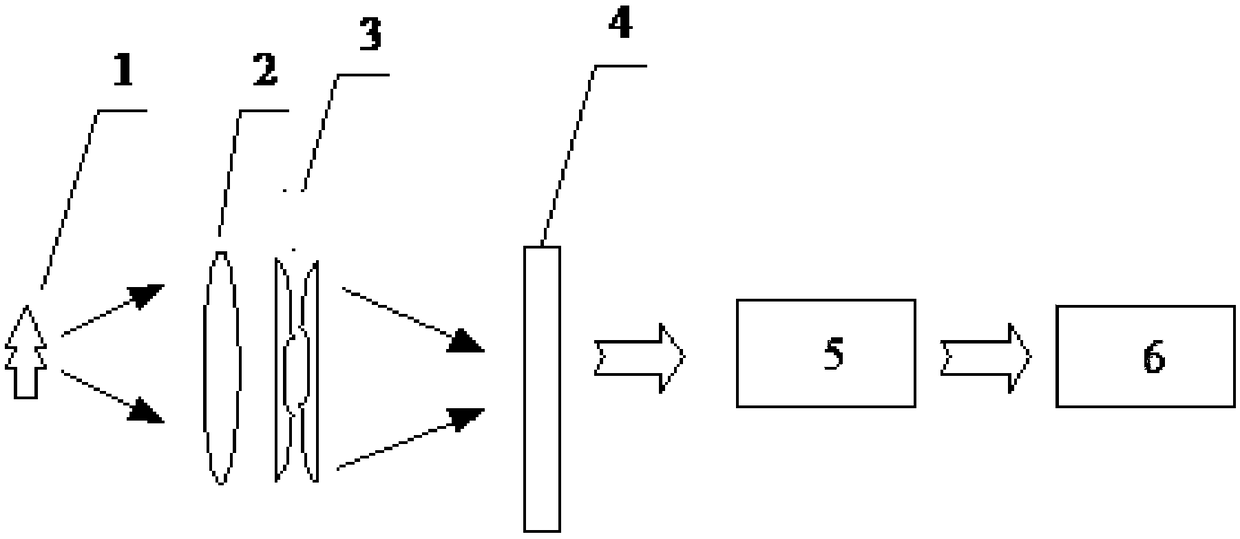
[0085] refer to figure 1 , the system includes an imaging lens 2, a composite phase mask 3, an image detector 4, and an image processing unit 5 arranged sequentially along the transmission direction of the optical axis;

[0086] The composite phase mask is composed of two generalized cubic phase components superimposed along the transmission direction of the optical axis, and the two generalized cubic phase components can be rotated independently and the rotation direction and angle can be different;

[0087] In the system proposed by the present invention, after the target 1 passes through the imaging lens 2 and the composite phase mask 3, a blurred intermediate image is formed on the image detector 4, and then the image processing unit 5 performs deconvolution processing to finally obtain the focus Clear image6.

[0088] The biggest difference between the dynamic wavefro...


PUM


Abstract

The invention belongs to the technical field of optics, and specifically relates to a phase-mask-adjustable dynamic wavefront coding imaging system. The phase-mask-adjustable dynamic wavefront codingimaging system can switch between conventional maskless imaging and multiple mask imaging according to actual demands, can implement a flexible and controllable depth of field expansion range and restoration of image quality, and can improve the ability to recognize different types of targets by means of directional filtering when applied to long-wave infrared imaging. The phase-mask-adjustable dynamic wavefront coding imaging system includes an imaging camera, a composite phase mask plate, an image detector and an image processing unit, wherein the imaging camera, the composite phase mask plate, the image detector and the image processing unit are arranged successively in the optical axis transmission direction. The composite phase mask plate is formed by stacking of two generalized cubicsquare phase assemblies in the optical axis transmission direction, and the two generalized cubic square phase assemblies can generate different phase modulation intensity through individual rotation.

Description

technical field [0001] The invention belongs to the field of optical technology, and in particular relates to a dynamic wavefront encoding imaging system with an adjustable phase mask. Background technique [0002] The depth of field of extended optical systems has always been a hotspot in academic research. Since the mid-1980s, although various methods have been proposed for depth of field expansion, it was not until Dr. Dowski and Professor Cathey of the University of Colorado in the United States proposed the wavefront in 1995. After the concept of coding, the extension of depth of field had a real breakthrough. [0003] At present, the wavefront encoding imaging system is mostly applied in a static manner, that is, the phase mask cannot dynamically change its physical form after the design is finalized, and the possible problems caused by this are as follows: [0004] First of all, regardless of whether the target to be imaged exceeds the depth of field of the original ...

Claims


Application Information

Patent Timeline
Patent Type & Authority Applications(China)
IPC IPC(8): G02B27/00G02B26/06
CPCG02B26/06G02B27/00
Inventor 赵惠魏静萱樊学武夏晶晶张凌
Owner XI'AN INST OF OPTICS & FINE MECHANICS - CHINESE ACAD OF SCI
Learn More