Process damping modeling method for thin-walled part milling

A modeling method and technology of thin-walled parts, applied in special data processing applications, instruments, electrical digital data processing, etc., can solve the problem of inability to model reasonably the damping of the small radial depth of cut milling process, and achieve the effect of process damping , the effect of improving the prediction accuracy

Active Publication Date: 2018-11-13
NORTHWESTERN POLYTECHNICAL UNIV
View PDF5 Cites 7 Cited by
  • Summary
  • Abstract
  • Description
  • Claims
  • Application Information

AI Technical Summary

Problems solved by technology

[0006] In order to overcome the defect that the existing method only considers the vibration in the feed direction and ignores the vibration effect in the normal direction of the feed in the process of modeling the process damping of thin-walled parts, and cannot properly model the damping of the small radial depth of cut milling process. , the present invention proposes a process damping modeling method suitable for the milling process of thin-walled parts and considering the vibration effects of two orthogonal directions at the same time

Method used


Image

  • Process damping modeling method for thin-walled part milling
  • Process damping modeling method for thin-walled part milling
  • Process damping modeling method for thin-walled part milling

Examples


Embodiment Construction

[0042] Now in conjunction with embodiment, accompanying drawing, the present invention will be further described:

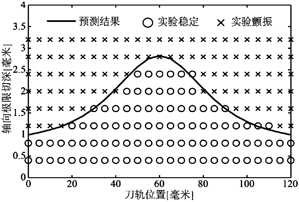
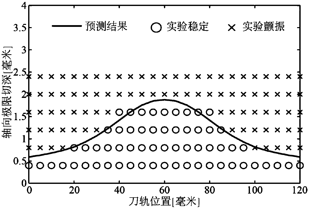
[0043] The number of teeth selected in the experiment is N=4 teeth, the radius R=6 mm, the helix angle β=30 degrees, and the normal forward angle α n = 10 degrees, the flat-bottomed carbide end mill with relief angle γ = 7 degrees adopts the down-milling cutting method in the three-coordinate vertical machining center, and the radial depth of cut is a e = 0.6 mm, the cutting parameters of feed per tooth c = 0.05 mm / tooth were used for the milling test of aluminum alloy thin-walled parts.

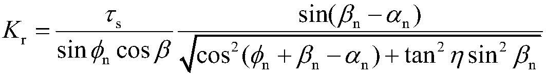
[0044] Step 1. Refer to the cutting data disclosed in the right-angle cutting parameter library to determine the material physical parameter φ n , β n and τ s(Refer to the literature "M. Kaymakci, Z.M. Kilic, Y. Altintas, Unified cutting force model forwarding, boring, drilling and milling operations, International Journal of Machine Tools and Manufacture 54-55 (2012) 34-45"...


PUM


Abstract

The invention relates to a process damping modeling method suitable for a thin-walled part milling process, which considers vibration effects of two orthogonal directions at the same time. The processdamping modeling method suitable for the thin-walled part milling process comprises the following steps: firstly, calculating a dynamic cutting force matrix and a process damping matrix correspondingto each edge element considering the vibration effects of the two directions at the same time; then combining the dynamic cutting force matrix and the process damping matrix of each edge element to calculate the dynamic cutting force matrix and the process damping matrix applied on the whole tool-workpiece system; and then using the obtained dynamic cutting force matrix and process damping matrixto establish a milling dynamic control equation of the tool-workpiece system, so that a stability lobe diagram considering the damping effect of the milling process of the thin-walled part can be drawn by performing stabilized solving on the equation.

Description

technical field [0001] The invention belongs to the field of electromechanical technology, and relates to a damping modeling method in milling process, in particular to a process damping modeling method applicable to the milling process of thin-walled parts. Background technique [0002] The classical process damping model believes that the cause of process damping is that the tool nose arc and flank face are pressed into the workpiece material, and are squeezed and rubbed against the workpiece. For very stiff, non-thin-walled parts, the plow cut model described above models process damping well. For thin-walled parts, due to the poor rigidity of the workpiece, the workpiece is easily deformed during processing to resist the action of the tool; at this time, the arc of the tool tip and the flank face are difficult to press into the workpiece material and produce strong extrusion and friction effect, the classical plow-cut theory is no longer applicable. Therefore, it is of...

Claims


Application Information

Patent Timeline
Patent Type & Authority Applications(China)
IPC IPC(8): G06F17/50
CPCG06F30/17
Inventor 万敏冯佳张卫红高挺岐
Owner NORTHWESTERN POLYTECHNICAL UNIV
Why Eureka
Try Eureka