Interphase insulation paper, stator core and coil insertion machine

A technology of phase-to-phase insulation and stator core, applied in the direction of laying solid insulation, shape/style/structure of winding insulation, etc., can solve problems such as coil wire leakage, and achieve the effect of less insulation failure

Inactive Publication Date: 2020-05-22
ETEC
View PDF10 Cites 1 Cited by
  • Summary
  • Abstract
  • Description
  • Claims
  • Application Information

AI Technical Summary

Problems solved by technology

When the end of the coil is crushed, the coil wires arranged in the stator core bulge to the side. Although it is very rare, the coil wires may still cross the interphase insulating paper and bundle to the adjacent coils in the slot. area leak

Method used


Image

  • Interphase insulation paper, stator core and coil insertion machine
  • Interphase insulation paper, stator core and coil insertion machine
  • Interphase insulation paper, stator core and coil insertion machine

Examples


no. 1 example

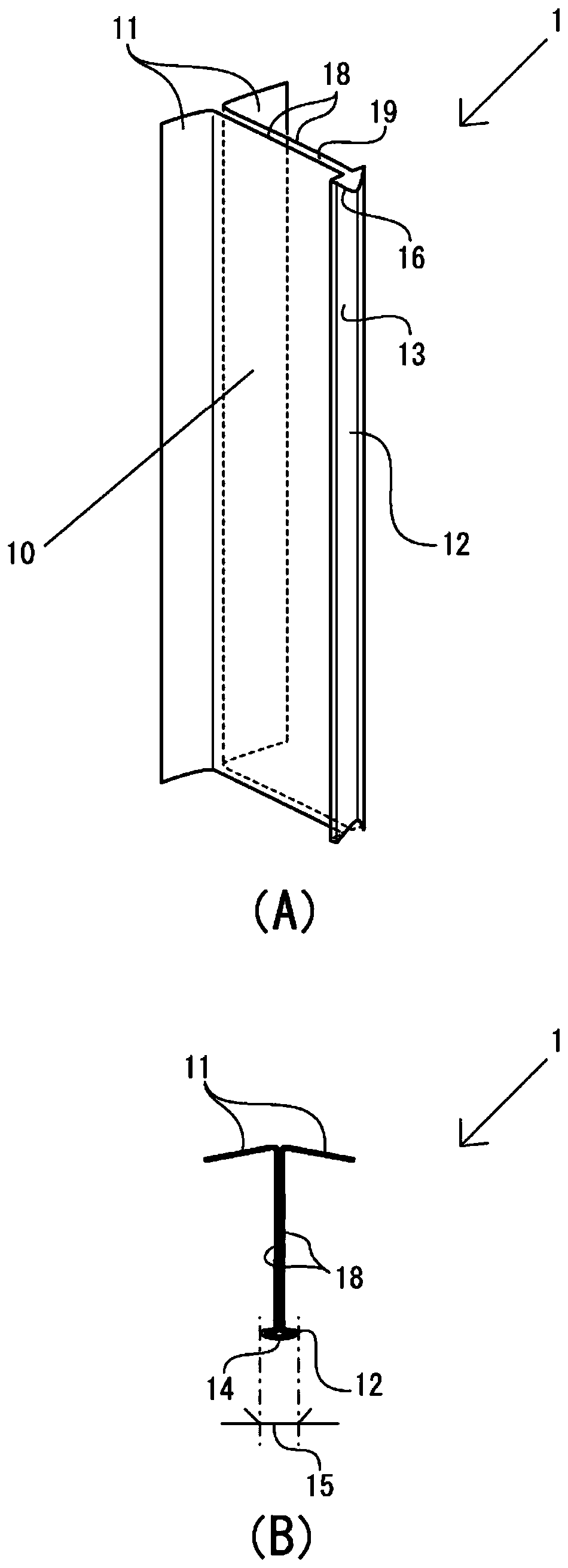
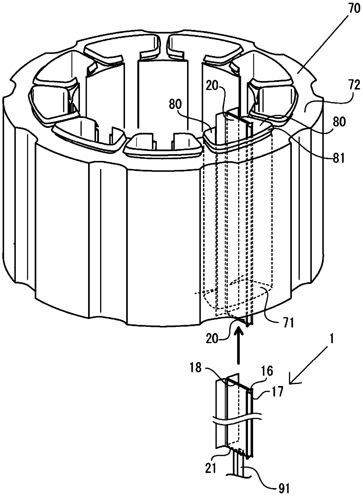
[0060] In the first embodiment, refer to Figure 1 to Figure 8 , the interphase insulating paper 1 , the stator core to which the interphase insulating paper 1 is attached, and the coil insertion machine 200 will be described. The plate body 13 on the outer surface side among the plate bodies is bent. figure 1 (A) is a perspective view showing the interphase insulating paper 1, figure 1 (B) in (B) is a cross-sectional view showing the interphase insulating paper 1 . figure 2 It is a schematic diagram illustrating insertion of the interphase insulating paper 1 into the slot 71 of the stator core 70 .

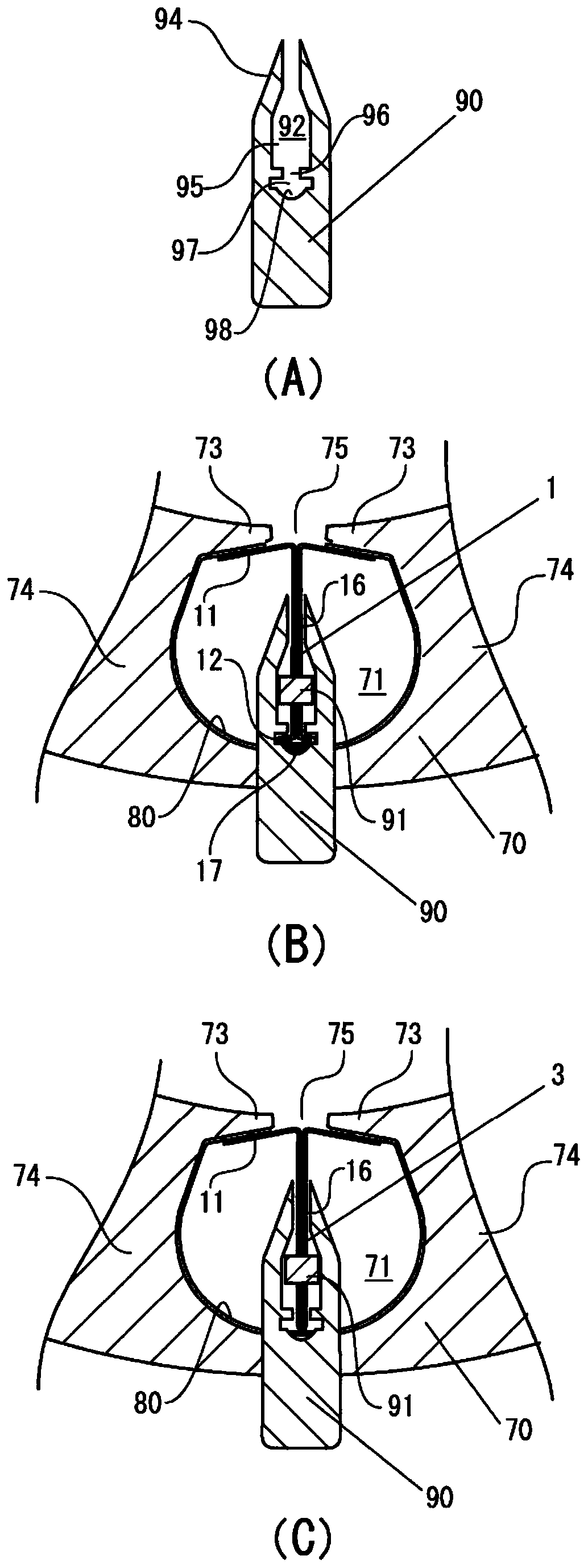
[0061] image 3 (A) in (A) is a sectional view showing the interphase insulating paper guide member 90, image 3 (B) in and image 3 Each figure of (C) is a figure for explaining the position between the slot 71, the interphase insulating paper guide member 90, and the interphase insulating paper 1. image 3 (B) in and image 3 Each figure in (C) is shown from Figure 4 ...

no. 2 example

[0085] In the second embodiment, refer to Figure 9 , the interphase insulating paper 2 in which the convex shape of the radially outer plate body 24 on the front side of the radially outer bent portion is crushed and the thickness of the insertion guide portion 25 is thin will be described briefly. When the interphase insulating paper 2 is bent by the bending die, only the front side becomes the insertion guide part 25 which is heated and compressed in the thickness direction and crushed to form a thin sheet thickness. By making the insertion guide portion 25 thin, when the interphase insulating paper 2 is inserted, the front side portion 26 of the interphase insulating paper is not caught by the first insulating paper, and the insertion is smooth.

[0086] In addition, since only the insertion guide portion 25 is heated and compressed, almost the entire length of the outer-diameter-side bent portion 12 is always in a state of protruding outward, and the first insulating pape...


PUM


Abstract

[Problem] To provide an interphase insulating paper, a stator core, and a coil insertion machine in which a coil wire is not susceptible to leakage to an adjacent phase within a slot, not only during coil insertion, but also during edge part processing of a coil end part. [Solution] An interphase insulating paper in which a pair of narrow plates having electrical insulating properties are folded in two so as to be bilaterally symmetric. An inner-diameter-side folded part that is folded so as to project to one side is provided at both end parts of the interphase insulating paper along a flange part. An outer-diameter-side folded part folded in an overlapping manner so as to project at both sides is provided at the fold center of the interphase insulating paper. The inner-diameter-side folded part and the outer-diameter-side folded part are brought into contact with a first insulating paper disposed along the inner circumference of the slot, partitioning the slot into two coil winding spaces.

Description

technical field [0001] The invention relates to an interphase insulating paper inserted into slots of an armature. In more detail, it relates to an interphase insulating paper, a stator core inserted with the interphase insulating paper, and a coil insertion machine for inserting the interphase insulating paper into the stator core, wherein the interphase insulating paper is formed into a stator iron core Coil wires wound in concentrated winding and forming different phases are insulated from adjacent tooth portions of the slots of the core. Background technique [0002] The coil bundles wound so as to form different phases on adjacent teeth forming the armature are adjacent to each other in the slots, and therefore electrical insulation breakdown may occur due to contact of the coil wires. In order to prevent insulation breakdown, an interphase insulating paper is arranged in the slots to insulate adjacent coil bundles that form phases and are wound around the respective t...

Claims


Application Information

Patent Timeline
Patent Type & Authority Patents(China)
IPC IPC(8): H02K3/34H02K15/10
CPCH02K3/34H02K15/10
Inventor 细野圣二稻叶洋二
Owner ETEC
Why Eureka
Try Eureka