Brake device of double-bearing reel

A braking device and reel technology, which is applied to fishing reels, fishing, applications, etc., can solve the problems of complicated device assembly and poor insulation, and achieve the effects of easy assembly and alleviation of poor insulation.

Active Publication Date: 2004-08-04
SHIMANO INC
View PDF1 Cites 13 Cited by
  • Summary
  • Abstract
  • Description
  • Claims
  • Application Information

AI Technical Summary

Problems solved by technology

In this way, when the wire is connected to the coil, the double-bearing reel used in a corrosive atmosphere with a lot of moisture is prone to poor insulation.
Furthermore, since the coil is mounted on the reel body so as to be movable in the direction of the spool axis, the coil must be mounted on the reel body and the circuit board must be mounted on the reel body, and the assembly of the device becomes troublesome

Method used


Image

  • Brake device of double-bearing reel
  • Brake device of double-bearing reel
  • Brake device of double-bearing reel

Examples


no. 1 Embodiment approach

[0052] First embodiment (R3526, 3527)

[0053] 〔The composition of the reel〕

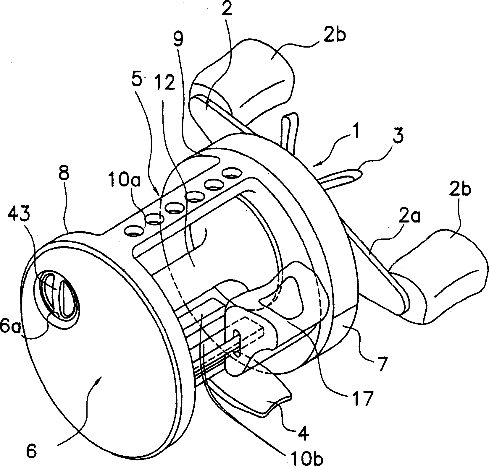
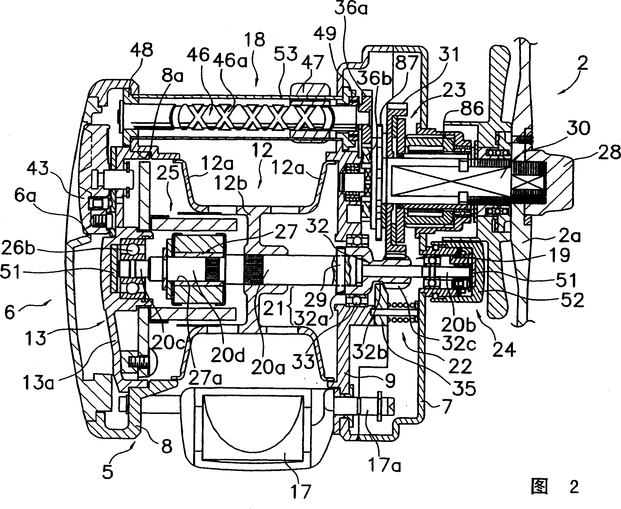
[0054] in figure 1 As shown in Fig. 2, the double-bearing reel obtained by one embodiment of the present invention is a round double-bearing reel for bait casting. The reel has: a reel body 1, a handle for reel rotation arranged on the side of the reel body 1, 2, a star traction for traction adjustment on the side of the reel body 1 arranged on the handle 2器3.

[0055] The handle 2 is a double handle-shaped member having a plate-shaped arm portion 2a and a handle 2b rotatably attached to both ends of the arm portion 2a. As shown in FIG. 2, the arm portion 2a is mounted on the front end of the handle shaft 30 so as not to rotate, and is fastened to the handle shaft 30 by a nut 28.

[0056] The reel main body 1 is a member made of metal such as aluminum alloy or magnesium alloy, and includes a member 5 and a first side cover 6 and a second side cover 7 mounted on both sides of the member 5. The reel 12 f...

no. 2 Embodiment approach

[0120] Second embodiment (R3580)

[0121] In the aforementioned first embodiment, although the insulating film 90 is formed on the entire circuit board 70, the insulating film 190 may be selectively formed. In addition, in the following description, the description of the same or equivalent configuration and operation as the first embodiment is omitted.

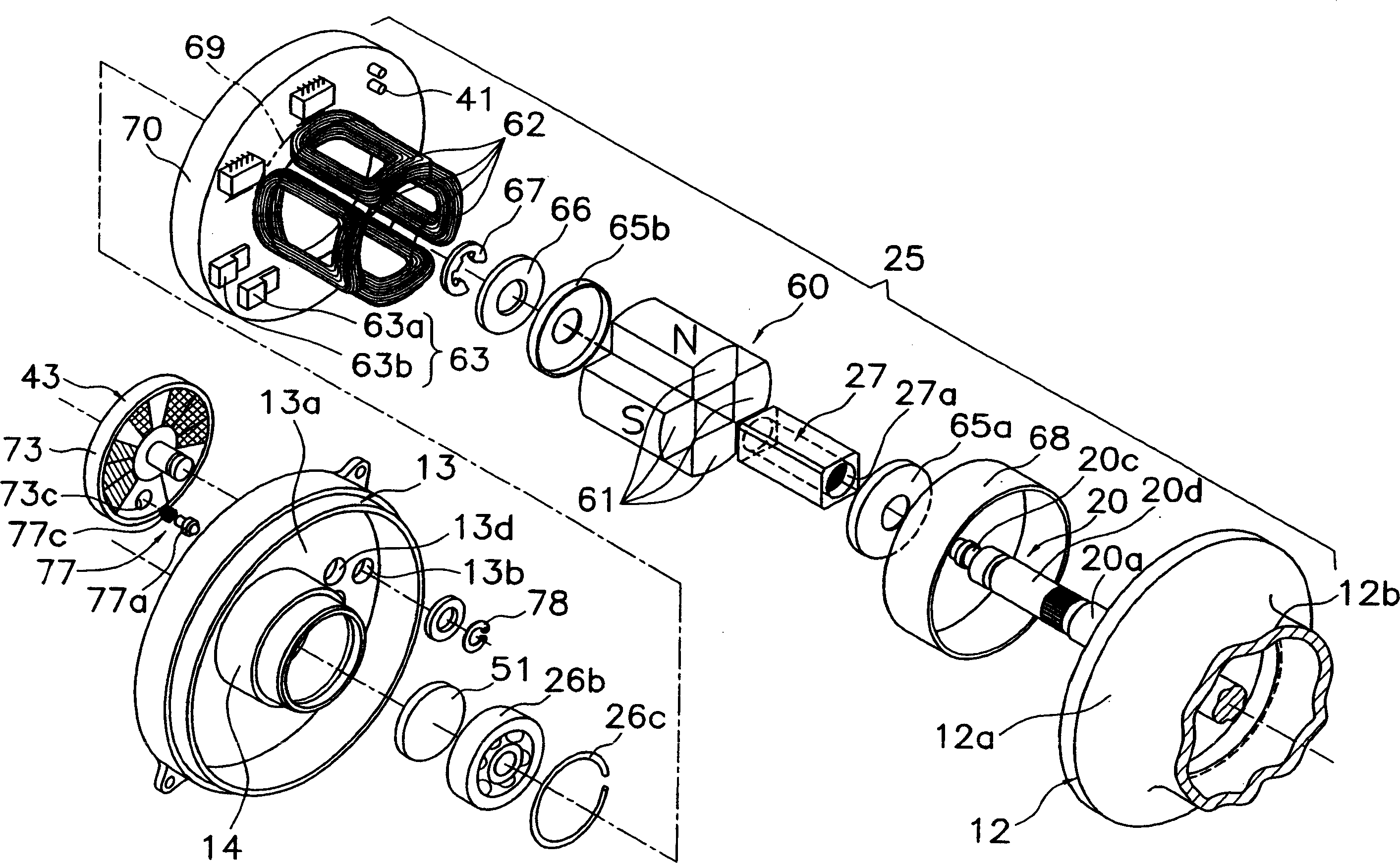
[0122] in Figure 12 ~ Figure 1 In 4, the switching element 63 has two FETs (Field Effect Transistors) 63a and 63b which can be switched at high speed and are connected in parallel. The coil 62 connected in series is connected to the drain terminals of the FETs 63a and 63b. Such as Figure 14B As shown, the switching element 63 is mounted on the back surface of the circuit board 70 (the surface on the opposite side to the surface facing the flange portion 12a).

[0123] The rotation speed sensor 41 uses, for example, a reflective photoelectric sensor 44 having a light projecting portion 44a and a light receiving portion 44b, and ...

no. 3 Embodiment approach

[0132] [Third Embodiment] (R3572)

[0133] In the third embodiment, a case where the molded insulating film 290 is formed by a hot melt molding method will be described. In addition, in the following description, descriptions of configurations and operations that are the same as or equivalent to those of the first and second embodiments are also omitted.

[0134] in Figure 16 As shown in FIG. 17, in the third embodiment, the switching element 63 has, for example, two FETs (Field Effect Transistors) 63a and 63b that can be controlled at high speed and connected in parallel. The coil 62 connected in series is connected to the drain terminals of the FETs 63a and 63b. Such as Figure 17B As shown, the switching element 63 is mounted on the back surface of the circuit board 70 (the surface on the opposite side to the surface facing the flange portion 12a).

[0135]The circuit board 70 is a ring-shaped board having a washer shape with a circular center opening, and is arranged substant...


PUM


Abstract

A braking device for a dual bearing reel includes a spool braking unit (40) and a spool control unit (42). The spool braking unit includes a rotor element (60) that rotates in association with the spool (12) and includes a plurality of magnets (61) sequentially arranged in the rotational direction, a plurality of serially connected coils (62) that are disposed around a periphery of the rotor element in a circumferential direction, and a switch element (63) that is connected to both ends of the plurality of the serially connected plurality of coils. The spool control unit electrically controls the spool braking unit, and includes a circuit board (70) on which the plurality of coils are installed and which is mounted on the reel unit, and a controller(55) that is mounted on the circuit board.

Description

Technical field [0001] The present invention relates to a braking device, in particular to a braking device of a double-bearing reel for braking a reel rotatably mounted on a reel main body. Background technique [0002] A double-bearing reel, especially a bait reel that is thrown with bait and other fishing equipment installed at the tip of the fishing line, is equipped with a brake to brake the reel in order to prevent rewinding during throwing. Device. Among such braking devices in the prior art, most of them are mechanical devices that utilize centrifugal force or magnetic force. However, in a mechanical braking device, because only a braking force proportional to or squarely proportional to the rotation speed is generated, the braking force is also generated during the time when the braking is not originally required, and there is a concern that the throwing distance may be reduced. [0003] Therefore, an electric control type brake device is known that provides a power gene...

Claims


Application Information

Patent Timeline
Patent Type & Authority Applications(China)
IPC IPC(8): A01K89/033A01K89/0155
CPCA01K89/01555A01K89/033
Inventor 生田刚川崎宪一平泉一城
Owner SHIMANO INC
Why Eureka
Try Eureka