Transfer case structure and hinge joint type dumper

A transfer case and articulated technology, which is applied to vehicles, vehicle components, fluid steering mechanisms, etc. that are inclined to carry motion, can solve the problems of large influence of the transmission shaft angle, insufficient steering force, and loss of control of the whole vehicle, so as to improve driving. The effect of safety, improved passing ability, and reliable performance

Pending Publication Date: 2018-11-16
XUZHOU XCMG MINING MACHINERY CO LTD
View PDF0 Cites 0 Cited by
  • Summary
  • Abstract
  • Description
  • Claims
  • Application Information

AI Technical Summary

Problems solved by technology

[0004] 1. Torque distribution cannot be customized, it can only be front and rear 1:1 output, but according to the gravity distribution of articulated dump trucks, it is better to distribute the front and rear output torque at about 1:2, the most ideal state is according to each The load of the bridge is distributed in the same proportion
[0005] 2. The differential is located on the bottom shaft of the transfer case, and the front and rear outputs are coaxial. There are two problems with this arrangement: a. The size of the front and rear space of the bottom output shaft of the transfer case increases, and the transfer case reaches the front The transmission shaft of the bridge becomes shorter, and the up and down fluctuation of the front axle has a great influence on the angle of the transmission shaft, and the processing of the shorter transmission shaft is difficult and costly;

Method used


Image

  • Transfer case structure and hinge joint type dumper
  • Transfer case structure and hinge joint type dumper
  • Transfer case structure and hinge joint type dumper

Examples


Example Embodiment

[0036] The present invention will be further described below in conjunction with the drawings. The following implementations are only used to illustrate the technical solutions of the present invention more clearly, and cannot be used to limit the protection scope of the present invention.

[0037] The transfer case structure of the embodiment of the invention can be used in the articulated dump truck of the embodiment of the invention; the articulated dump truck of the embodiment of the invention has the transfer case structure of the embodiment of the invention.

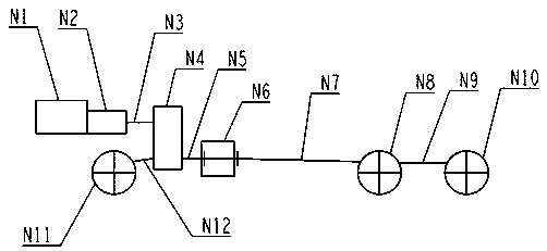
[0038] Such as figure 1 As shown, the power source is the engine N1, which is geared through the gearbox N2 to control the driving speed and driving force. The power output by the gearbox N2 is transmitted to the transfer case N4 through the transmission shaft N3, and the transfer case N4 passes through the transmission shaft N12. And the drive shaft N5 transmits power to the front axle N11 and the articulated body N6. ...


PUM


Abstract

The invention discloses a transfer case structure applied to a hinge joint type dumper. The transfer case structure comprises a case body, an input shaft, a differential mechanism, a rear output gearassembly I, a front output gear assembly I, a rear output gear assembly II, a front output gear assembly II and a front output gear assembly III. The differential mechanism is located on an upmost shaft of a transfer case, and the differential mechanism and the input shaft of the transfer case are coaxial; the input shaft transmits power to the differential mechanism, and the differential mechanism distributes the power to the rear output gear assembly I and the front output gear assembly I; the rear output gear assembly I is engaged with the rear output gear assembly II, and the power is output to a hinge joint body; and the front output gear assembly I is engaged with the front output gear assembly II, and the front output gear assembly II is engaged with the front output gear assembly III, so that the power is output to a front axle. The front and back spatial size of a lowest shaft of the transfer case is reduced, and output from the transfer case to the front axle can be improved;and fixed proportional distribution of the front and back output torque can be achieved.

Description

technical field [0001] The invention relates to a transfer case structure, which belongs to the technical field of transmission. Background technique [0002] Articulated dump truck is a special equipment specially used in harsh working conditions such as rainy, muddy, and rough roads. It has front and rear frames, which are connected by hinged bodies or swing rings. Components such as the cab are supported by the front axle, and the cargo compartment is arranged on the rear frame, which is supported by the middle axle and the rear axle. Such as figure 1 A schematic diagram of the power transmission of an articulated dump truck is shown. Special operating conditions require articulated dump trucks to have excellent driving ability and off-road capability, and most of them are three-axle all-wheel drive. When the cargo compartment is fully loaded, the load capacity of the three axles is basically the same, or the middle and rear axles are slightly higher. The transfer cas...

Claims


Application Information

Patent Timeline
IPC IPC(8): B60K17/346B60P1/04B62D5/06
CPCB60K17/346B60P1/04B62D5/06
Inventor 秦红义张杰山汤治明王道明
Owner XUZHOU XCMG MINING MACHINERY CO LTD
Why Eureka
Try Eureka