Main truss surface installation and construction method

A construction method and main truss technology, which is applied in the direction of erecting/assembling bridges, buildings, bridge construction, etc., can solve the problems of high center of gravity, complex structure, and high safety risk of hanging baskets, and achieve low construction difficulty coefficient, simplify construction procedures, Reduce the effect of tip displacement

Active Publication Date: 2020-04-28
GUIZHOU ROAD & BRIDGE GRP
View PDF5 Cites 0 Cited by
  • Summary
  • Abstract
  • Description
  • Claims
  • Application Information

AI Technical Summary

Problems solved by technology

[0004] The displacement of the front end of the existing hanging basket is relatively large, which increases the difficulty of cantilever construction control; the center of gravity of the existing hanging basket is relatively high, and there are problems of poor running and working stability of the hanging basket; the rear anchor part of the hanging basket currently on the market needs a corresponding mechanism To ensure the reliability of anchoring, the structure is more complicated and the safety risk is greater; the height of the main truss of the existing hanging basket is too large, generally exceeding 3m, but the height of the main truss of the hanging basket under the bridge is affected by the water level or ground elevation When it is less than 1m, or even tens of centimeters, and you don’t want to add extra engineering, the existing hanging basket is powerless

Method used


Image

  • Main truss surface installation and construction method
  • Main truss surface installation and construction method
  • Main truss surface installation and construction method

Examples


Embodiment Construction

[0030] The embodiments of the present invention will be described in detail below with reference to the accompanying drawings, but the present invention can be implemented in various ways defined and covered by the claims.

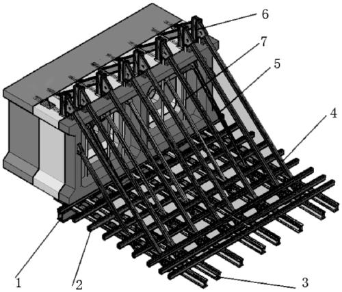
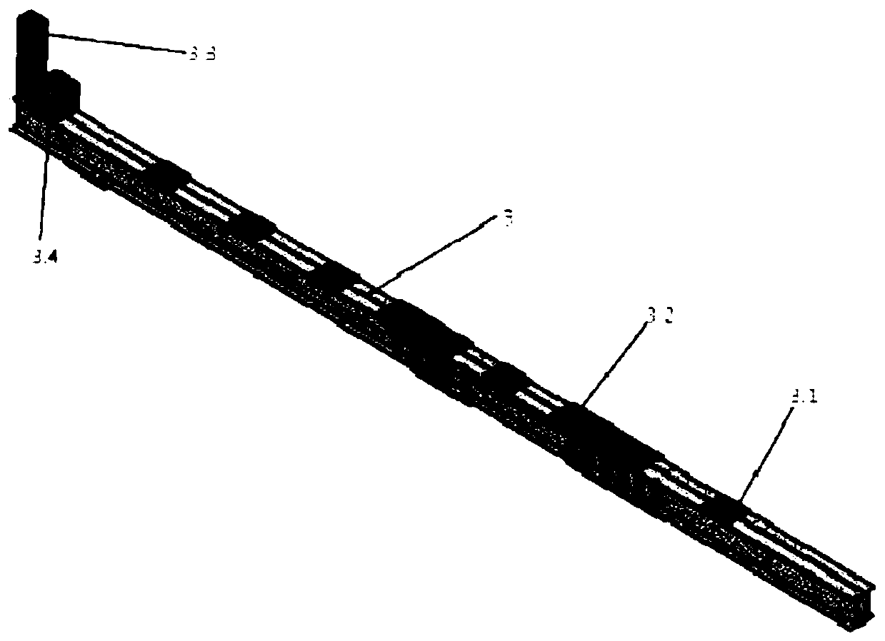
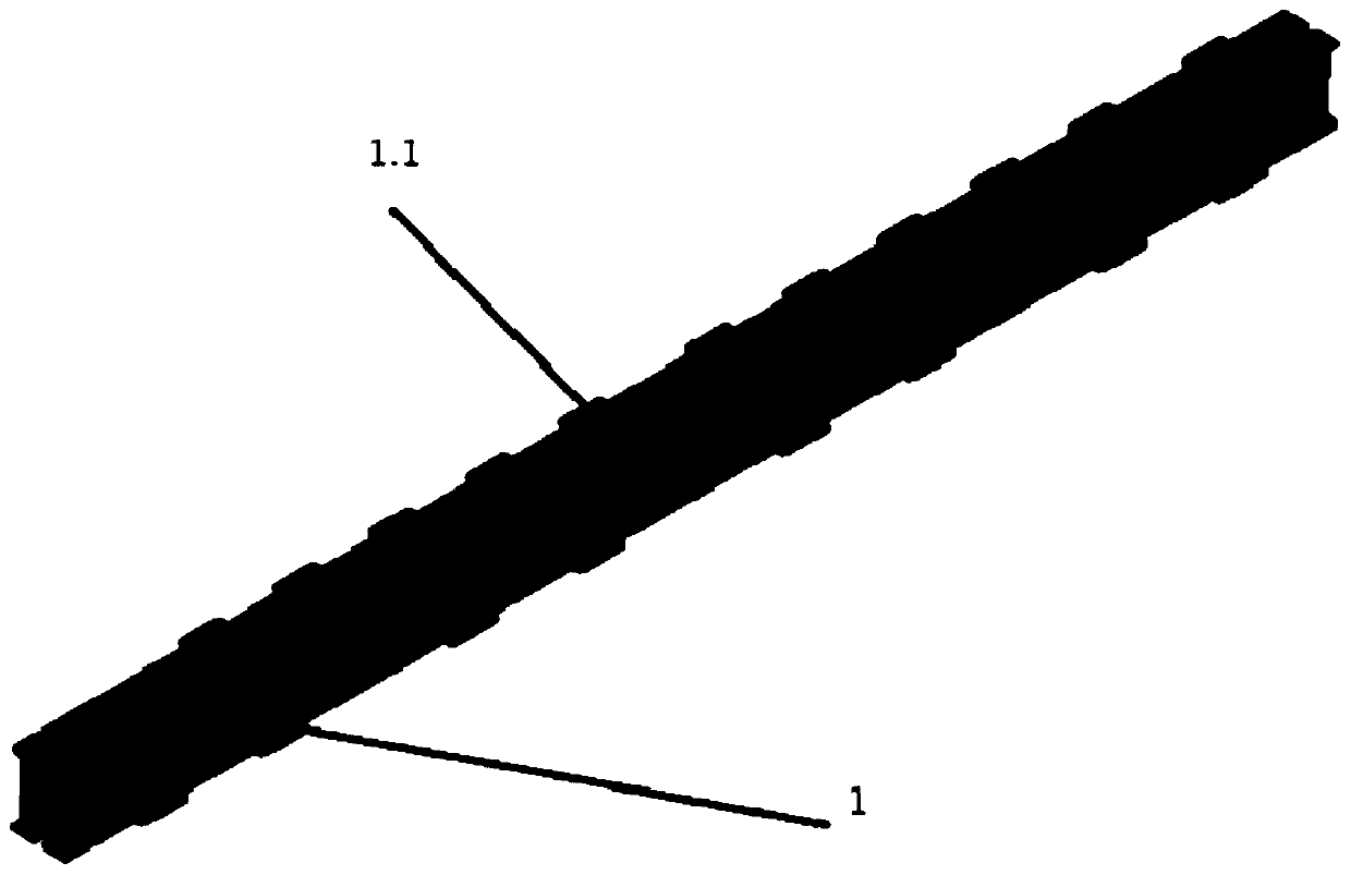
[0031] Main truss surface installation method, such as Figure 1-6 As shown, the main truss includes a main beam 1 , a secondary beam 2 , a longitudinal beam 3 , a steel sling system, a pre-embedded structure 6 and an anchor screw 7 . The number of the main beam 1 is one, the number of the secondary beams 2 is eight, and they are arranged on the longitudinal beams 3 at equal intervals, and the number of the longitudinal beams 3 is eight, and they are arranged at equal intervals. The invention has the advantages of small displacement of the front end of the hanging basket at the rear fulcrum, which reduces the control difficulty of hanging construction; the main truss of the hanging basket is lowered. The center of gravity of the hanging basket is low, and...


PUM


Abstract

The invention provides a main truss curved surface installation construction method, and belongs to the field of bridge construction. The main truss curved surface installation construction method includes the following steps that when rebar of a previous poured box arch section is constructed, machined pre-buried structures are arranged on the rebar on an end socket of in the previous poured boxarch section; box arch concrete is poured, an anchor lead screw hole is reserved, and an anchor lead screw is placed in the reserved anchor lead screw hole in a sleeved mode; a main beam is hoisted tothe bottom of the previous poured box arch section to be temporarily fixed, one ends of two front row slings at the two outer side ends of the section are fixed to the pre-buried structures on both sides of the previous poured box arch section, and the other ends of the two front row slings hoist two longitudinal beams at the outer side to mount and fix; a cross bar is used for being pre-fixed atthe other ends of the two longitudinal beams at the outer side, and longitudinal beams at middle are symmetrically and sequentially installed; secondary beams are installed across the longitudinal beams; and rear row slings are installed, and bottom formworks are placed on the secondary beams to form a main arch ring linear shape. The main truss curved surface installation construction method islow in construction difficulty coefficient, adopts a method of replacing curves by curves, and reduces the error of the arch ring arc-shaped linear shape.

Description

technical field [0001] The invention relates to the field of bridge construction, in particular to a construction method for installing a curved surface of a main truss. Background technique [0002] As an important equipment in the cantilever pouring construction method, the hanging basket plays the role of bearing the wet weight of the segment and providing a working platform during the concrete pouring process of the arch ring. Because the hanging basket is installed on the curved arch ring, its structure is quite different from the hanging basket structure used in continuous girder bridges, continuous rigid frame bridges and cable-stayed bridges. Whether the design of the hanging basket is reasonable will be directly related to the difficulty of construction, the quality of bridge construction and the progress of construction. For the assembly of the lower hanging basket affected by the water level or the cliff, it is impossible to use the existing hanging basket. There...

Claims


Application Information

Patent Timeline
Patent Type & Authority Patents(China)
IPC IPC(8): E01D21/00
CPCE01D21/00
Inventor 韩洪举郭吉平张基进肖黔
Owner GUIZHOU ROAD & BRIDGE GRP
Why Eureka
Try Eureka