Tunnel ventilation vertical shaft wellbore construction device and method

A technology of tunnel ventilation and construction device, which is applied to shaft equipment, shaft lining, well sinking, etc., can solve the problems of long construction period, slow construction speed, and difficulty in treatment of shotcrete cracking, and achieves good effect, improved construction speed, The effect of avoiding the problem of sprayed concrete cracking

Pending Publication Date: 2018-11-16
中煤第一建设有限公司第四十九工程处
View PDF0 Cites 3 Cited by
  • Summary
  • Abstract
  • Description
  • Claims
  • Application Information

AI Technical Summary

Problems solved by technology

In terms of structure, the middle partition of the shaft and the shaft are lined at the same time, and the integrity of the structure is good; in terms of project cost, the investment is relatively low, but in terms of construction speed, the initial support takes a long tim

Method used


Image

  • Tunnel ventilation vertical shaft wellbore construction device and method
  • Tunnel ventilation vertical shaft wellbore construction device and method
  • Tunnel ventilation vertical shaft wellbore construction device and method

Examples


Embodiment Construction

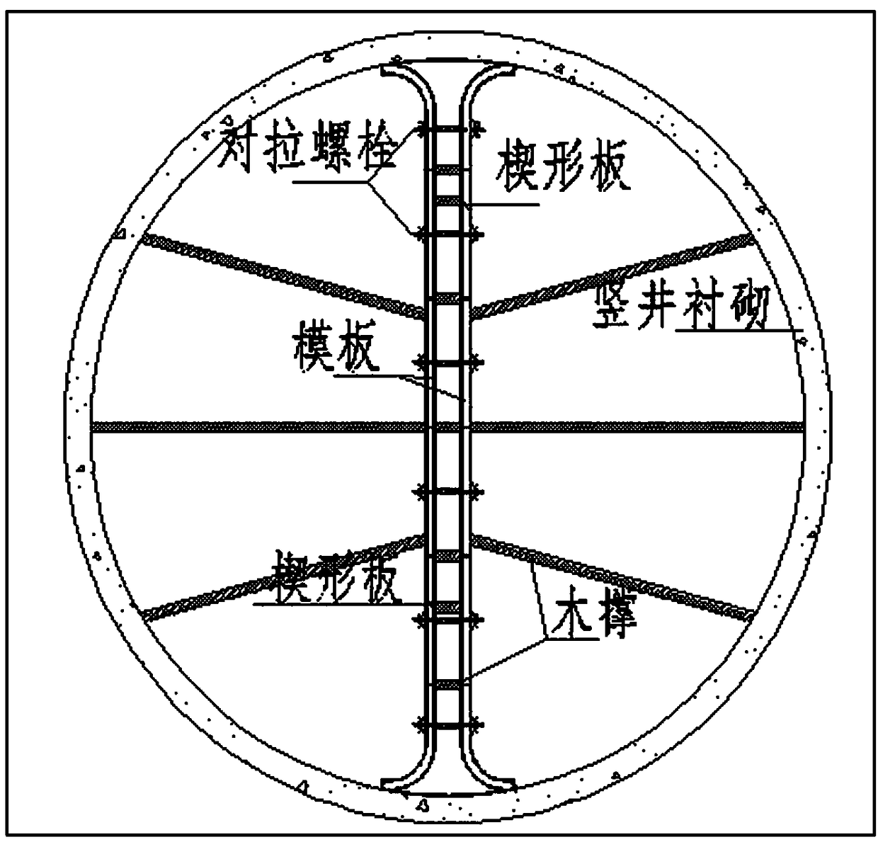
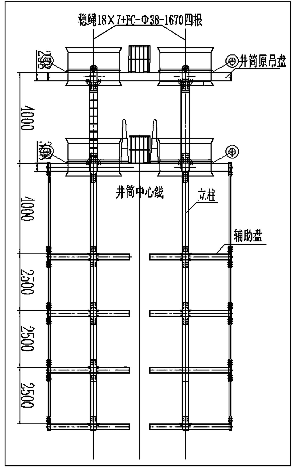
[0018] Such as figure 2 , 3 As shown, the tunnel ventilation shaft shaft construction device is composed of a shaft construction device and a partition construction device, wherein the shaft shaft construction device is an umbrella drill frame rock drill, the partition construction device includes a construction suspension plate and a formwork, and the shaft partition The construction adopts the prefabricated formwork, and the construction hanging plate of the middle partition is a six-layer hanging plate, of which the first and second hanging plates are double-layer hanging plates with an integral structure, and the third, fourth, fifth, and sixth layer hanging plates are all It is a split-type symmetrical crescent-shaped temporary hanging pan. The first and second hanging pans are equipped with fully enclosed guardrails and skirting boards. The third, fourth, fifth, and sixth hanging pans The upper part adjacent to the partition is provided with hinges to facilitate the as...


PUM


Abstract

A tunnel ventilation vertical shaft wellbore construction device is composed of a vertical shaft construction device body and a middle partition plate construction device body. The vertical shaft wellbore construction device body is an umbrella-shaped drilling rig rock drilling machine; the middle partition plate construction device body comprises a construction hanging scaffold and a formwork; construction of a wellbore middle partition plate adopts the fabricated formwork; the middle partition plate construction hanging scaffold is a six-layer hanging scaffold, wherein a first-layer hangingscaffold body and a second-layer hanging scaffold body are double-layer hanging scaffold body of an integral structure, and a third-layer hanging scaffold body, a fourth-layer hanging scaffold body, afifth-layer hanging scaffold body and a sixth-layer hanging scaffold body are each a split-type symmetric-crescent-shaped temporary hanging scaffold body; the first-layer hanging scaffold body and the second-layer hanging scaffold body are provided with fully-closed guardrails and skirting boards; folding hinges for facilitating erecting of the formwork are arranged at the positions, adjacent tothe partition plates, of the third-layer hanging scaffold body, the fourth-layer hanging scaffold body, the fifth-layer hanging scaffold body and the sixth-layer hanging scaffold body; guardrails andskirting boards are arranged at the positions, close to the wellbore, of the third-layer hanging scaffold body, the fourth-layer hanging scaffold body, the fifth-layer hanging scaffold body and the sixth-layer hanging scaffold body; middle partition plate pouring spaces are reserved in the first-layer hanging scaffold body and the second-layer hanging scaffold body; and gaps between the two crescent-shaped discs of the crescent-shaped third-layer hanging scaffold body, the crescent-shaped fourth-layer hanging scaffold body, the crescent-shaped fifth-layer hanging scaffold body and the crescent-shaped sixth-layer hanging scaffold body serve as middle partition plate pouring spaces of the third-layer hanging scaffold body, the fourth-layer hanging scaffold body, the fifth-layer hanging scaffold body and the sixth-layer hanging scaffold body.

Description

technical field [0001] The invention relates to a shaft construction method, in particular to a construction method for a tunnel ventilation shaft shaft and a middle partition. Background technique [0002] In recent years, the pace of my country's high-grade highway construction has been accelerating, and ventilation shafts are installed in extra-long tunnels to improve the environment and safety of the tunnels. Tunnel ventilation shafts are mostly dual-purpose in function, that is, a middle partition is installed inside the circular section to divide the shaft into two equal parts or four parts that are not equal, so as to meet the requirements of the two driving directions of the road tunnel. Air supply and exhaust needs. Usually, the shaft of the ventilation shaft adopts the initial support of anchor net cable spraying and the secondary lining concrete support, which determines that the initial support must be completed first during construction, and then the secondary ...

Claims


Application Information

Patent Timeline
IPC IPC(8): E21D1/08E21D5/12E21D5/11
CPCE21D1/08E21D5/11E21D5/12
Inventor 贾振刚刘彦杰白朝晖赵静
Owner 中煤第一建设有限公司第四十九工程处
Why Eureka
Try Eureka