Assembly method of carbon fiber composite truss main structure and fulcrum bar

A main structure and composite material technology, which is applied in the field of space optical remote sensing, can solve the problems of difficult processing, difficult processing, and large metal joints, and achieves easy control of thickness and uniformity, easy molding and assembly, and good thermal stability. Effect

Inactive Publication Date: 2018-11-16
CHANGCHUN INST OF OPTICS FINE MECHANICS & PHYSICS CHINESE ACAD OF SCI
View PDF5 Cites 11 Cited by
  • Summary
  • Abstract
  • Description
  • Claims
  • Application Information

AI Technical Summary

Problems solved by technology

[0003] 1. Metal joints are bulky, heavy, complex in structure, and difficult to process; especially when the joint is multi-way, the structure is more complicated and the processing is more difficult
[0004] 2. The support rod is glued together with the metal joint by socketing, and it is impossible to apply pressure to the glue joint, which makes it difficult to control the thickness and uniformity of the glue layer
[0005] 3. The materials of metal joints and composite poles are different. The deformation of metal expansion and contraction in high and low temperature environments is significantly higher than that of carbon fiber composite materials. The difference in deformation between the two materials seriously affects the overall stability of the truss structure

Method used


Image

  • Assembly method of carbon fiber composite truss main structure and fulcrum bar
  • Assembly method of carbon fiber composite truss main structure and fulcrum bar
  • Assembly method of carbon fiber composite truss main structure and fulcrum bar

Examples


Embodiment Construction

[0030] The present invention will be described in detail below in conjunction with the accompanying drawings.

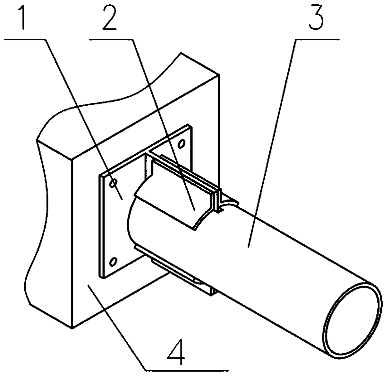
[0031] like Figure 1 to Figure 4 As shown, an assembly method of a carbon fiber composite truss main structure and struts, including a T-joint 1 and a bridging plate 2 .

[0032] Both the T-joint 1 and the bridging plate 2 are made of carbon fiber composite materials.

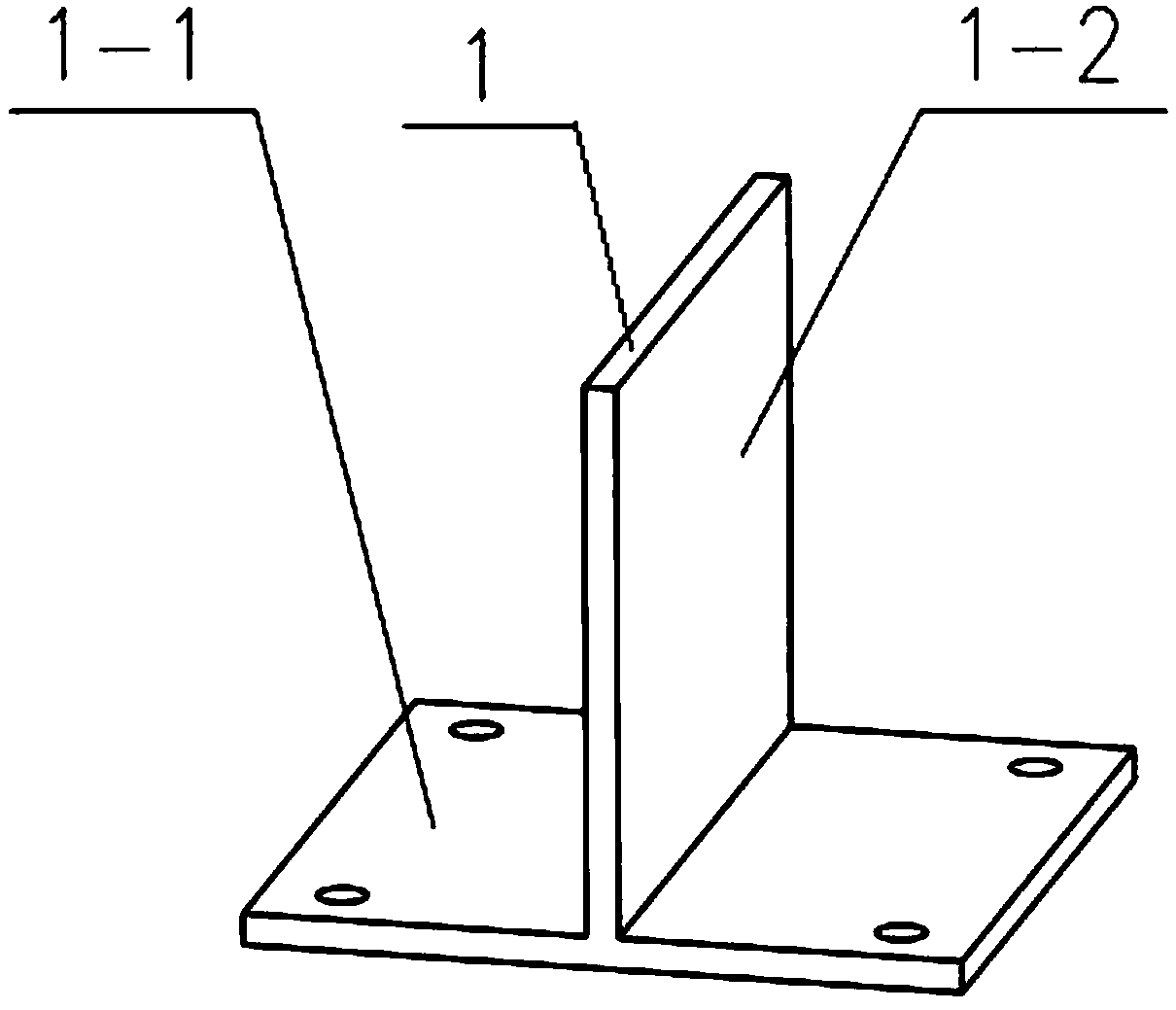
[0033] The T-joint 1 includes a mounting flange 1-1 and a thin-walled board 1-2, one end of the thin-walled board 1-2 is arranged on one side of the mounting flange 1-1, and the mounting flange 1-1 and the thin-walled The angle range between the boards 1-2 is 45° to 90°.

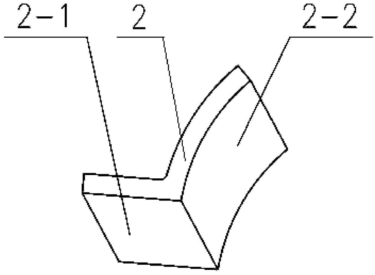
[0034] The bridging board 2 includes a bridging plane 2-1 and a bridging cylinder 2-2; four bridging boards 2 are evenly arranged on both sides of the other end of the thin-walled board 1-2. When the number of bridging boards is four, the implementation effect of the present invention is the best.

[0035] One end of the pole 3...


PUM


Abstract

The invention discloses an assembly method of a carbon fiber composite truss main structure and a fulcrum bar, and belongs to the field of space optical remote sensing. The assembly method aims to solve the technical problem that in the assembling process of a large-scale lightweight carbon fiber composite truss structure main structure and the fulcrum bar, the size is decreased, the mass is reduced, the processing difficulty is lowered, the uniformity of the thickness of a glue line is guaranteed, and at the same time, the overall stiffness and the stability of a truss are improved. The assembly method comprises a T-shaped joint, a bridging board and the fulcrum bar, and a thin wall inserting board of the T-shaped joint is inserted into slots of the fulcrum bar; a bridging plane of the bridging board is connected with the thin wall inserting board of the T-shaped joint in a cementing mode, a bridging cylinder plane is connected to the fulcrum bar in a cementing mode, and pressing andsolidification are carried out on cementing areas, so that the thin wall inserting board of the T-shaped joint is not in contact with the fulcrum bar; and a mounting flange is fixed to a truss main structure. According to the assembly method, the thickness and the uniformity of the glue line are easy to control, the size is small, the mass is light, the structure is simple, molding and assemblingare easy, and the carbon fiber composite truss structure is high in stiffness and good in heat stability.

Description

technical field [0001] The invention belongs to the field of space optical remote sensing and relates to an assembly method of a carbon fiber composite material truss main structure and a pole. Background technique [0002] The space truss structure composed of carbon fiber composite materials has the advantages of high specific stiffness, high specific strength, and good thermal stability, and has been widely used in space optical remote sensors. In the design of truss structures, it is inevitable to involve the assembly of a certain position of the main structure and the struts. The material and assembly method of the joint directly affect the mechanical and thermal properties of the entire truss structure. At present, the most commonly used assembly method is: a metal joint is set between the main structure and the strut, the strut is glued together with the metal joint by socketing, and the metal joint is assembled with the main structure by screwing. . This approach ...

Claims


Application Information

Patent Timeline
IPC IPC(8): F16B9/00F16B9/02
Inventor 徐宏杨利伟鲍赫樊延超庞新源
Owner CHANGCHUN INST OF OPTICS FINE MECHANICS & PHYSICS CHINESE ACAD OF SCI
Why Eureka
Try Eureka