Supercharge Your Innovation With Domain-Expert AI Agents!

Telescopic pipeline inner wall robot

A technology of telescopic pipes and robots, applied to special pipes, pipe components, mechanical equipment, etc., can solve problems such as stuck, rollover, complex structure, etc., and achieve the effect of avoiding blockage

Inactive Publication Date: 2018-11-16
BEIHANG UNIV
View PDF0 Cites 4 Cited by
  • Summary
  • Abstract
  • Description
  • Claims
  • Application Information

AI Technical Summary

Problems solved by technology

For the problems encountered by wheeled pipeline robots in the actual application process, such as motion interference in pipe bends and irregular pipelines, insufficient driving force due to internal friction, deformation of the wall and errors of the robot itself, the robot Deviating from the correct posture in the pipeline, even rollover and stuck
Researchers at home and abroad mainly solve the problem in terms of structure, such as the use of differential gear and flexible connection, but this will make the structure more complicated and increase the cost

Method used


Image

  • Telescopic pipeline inner wall robot
  • Telescopic pipeline inner wall robot

Examples


Embodiment 1

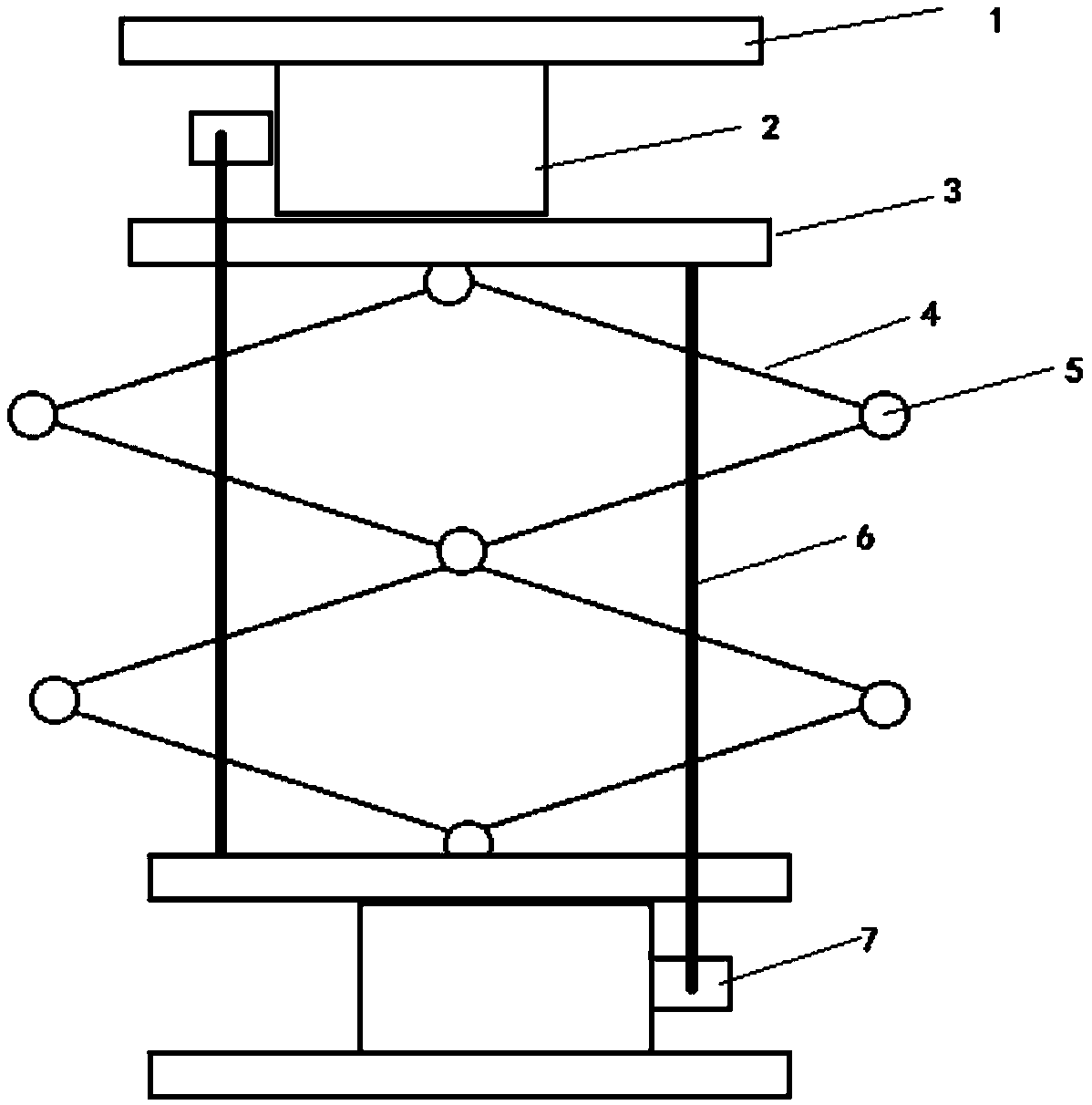
[0012] Such as figure 1 As shown in the telescopic structure shown, the functions of telescopic and bending are mainly realized. The basic principle of the structure is to use the instability of the quadrilateral to apply a force on the opposite corner of the quadrilateral to change the shape of the quadrilateral. If the tension is applied, the quadrilateral can be lengthened. If the pressure is applied, the shape of the quadrilateral can be changed. The quadrilateral is shortened to achieve the compression function. The bending function can be realized by connecting two such quadrilaterals through connectors. In our design, each side of the quadrilateral is made of hard material, and each corner of the quadrilateral has a spring 5 to provide a tendency for the telescopic structure to expand and contract. In this telescopic structure, the functions of the two geared motors 2 are basically similar to the geared motors in the software module 1. When the two geared motors 2 pul...

Embodiment 2

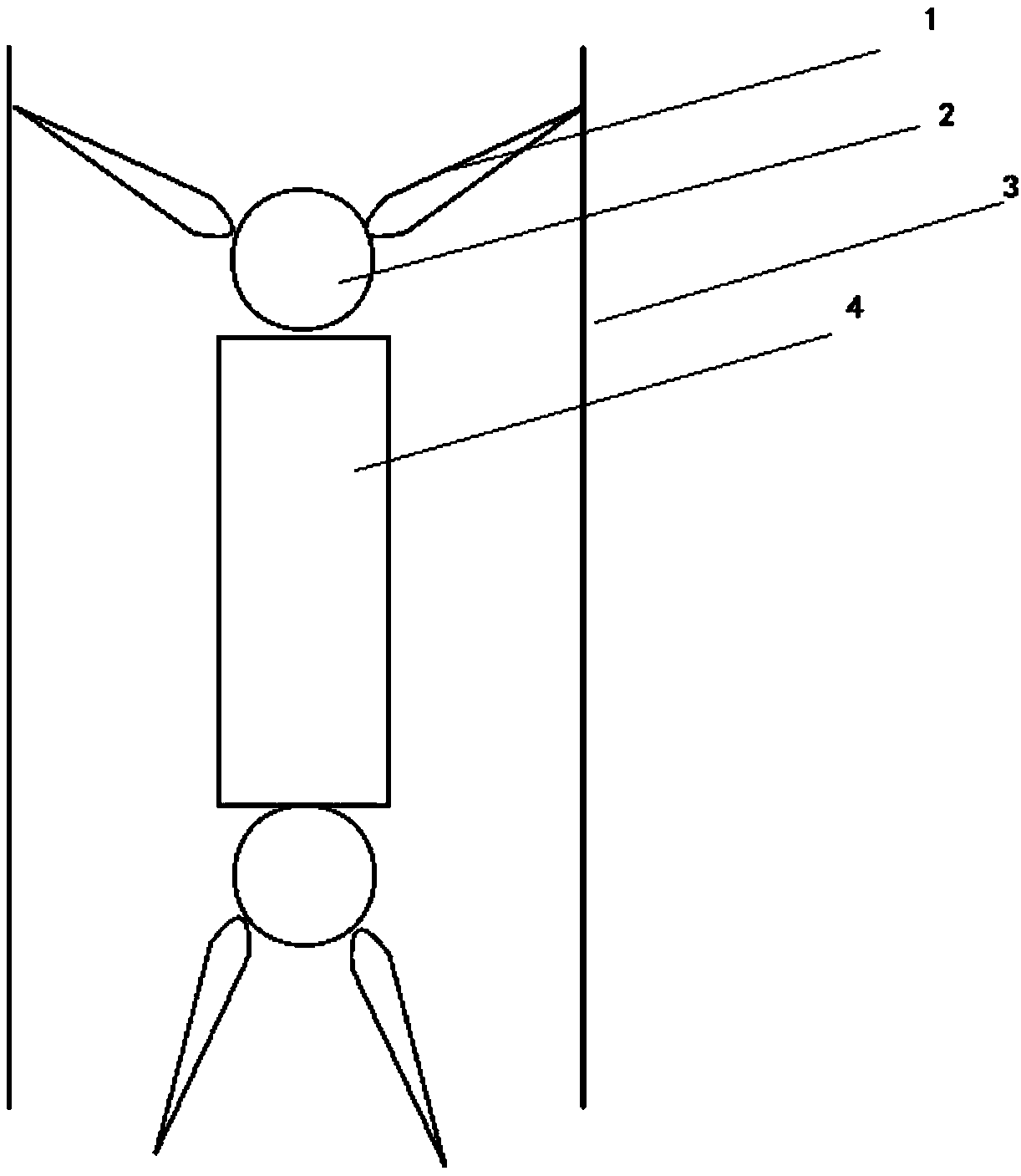
[0014] Such as figure 2 As shown, using the telescopic structure, we have designed a crawling robot on the inner wall of the pipe. The main purpose is to install support grippers 1 at both ends of the telescopic structure. This gripper is similar to the manipulator on the market. to a fixed effect. During our crawling process, the upper support gripper a works to support the inner wall of the pipeline, the lower support gripper b relaxes, and the contraction length of the telescopic structure 4 becomes smaller to lift the lower gripper; then the lower support gripper b Open the support gripper a on the top and draw it in, and stretch the telescopic structure 4 at the same time, so that the support gripper a is lifted, and climbing can be realized by reciprocating like this.


PUM


Abstract

The invention discloses a fiber rope type telescopic pipeline robot. The robot is mainly composed of a telescopic structure and supporting tongs. The main body of the telescopic structure is two parallelogram outer frames, only one connecting point is arranged between the two outer frames, torsion springs are arranged at each corner of the parallelogram, so that the parallelogram outer frames haveextending tendency; two speed reducing motors are arranged at the two ends of the telescopic structure, nylon ropes are connected to the two sides of the telescopic structure in a bridging mode, andpower is supplied through the speed reducing motors to enable the telescopic structure to be compressed. According to the robot, on the basis of the hard outer frames of the parallelogram structure, the elasticity of the torsion springs can enable the hard outer frames to extend, the speed reducing motors arranged at the two ends of the structure can compress the hard outer frames through the nylon ropes; a soft body can be bent by adjusting the rotating speed of the motors; and the supporting tongs are additionally arranged at the two ends of the telescopic structure so that crawling can be realized in a bent pipeline.

Description

technical field [0001] The invention relates to a solution for a pipeline crawling robot, which is a design scheme based on a fiber rope telescopic pipeline robot Background technique [0002] In the 1970s, the development of petroleum, chemical, natural gas and nuclear industries and the need for pipeline maintenance stimulated the research of in-pipe robots. It is generally believed that J.VR`ERTUT of France was the first to carry out research on the theory and prototype of in-pipe robots. He proposed the wheel-legged in-pipe walking mechanism model IPRIVO in 1978. In the 1980s, Toshio Fukuda, Hidemi Hosai, and Tokuji Okada in Japan , Qu Zhengxing, Fukuda Jinger and others made full use of the research results and modern technologies of France, the United States and other countries to develop intra-pipe robots with various structures. Hyouk R.C. of Sungkyunkwan University in South Korea and others developed the MRINSPECT series of natural gas pipeline inspection robots. ...

Claims


Application Information

Patent Timeline
IPC IPC(8): F16L55/32F16L55/40F16L101/10
CPCF16L55/32F16L55/40F16L2101/10
Inventor 李志虎辜智强王君来张玉玺
Owner BEIHANG UNIV
Features
  • R&D
  • Intellectual Property
  • Life Sciences
  • Materials
  • Tech Scout
  • Unparalleled Data Quality
  • Higher Quality Content
  • 60% Fewer Hallucinations
Learn More