New energy energy-saving and environment-friendly park illuminating lamp

An energy-saving, environmentally friendly, lighting technology, applied in lighting devices, lighting auxiliary devices, lighting and heating equipment, etc., can solve the problems of low photoelectric conversion efficiency, waste of electric energy, risk factor, etc.

Inactive Publication Date: 2018-11-16
肇庆中能创智信息科技有限公司
View PDF18 Cites 2 Cited by
  • Summary
  • Abstract
  • Description
  • Claims
  • Application Information

AI Technical Summary

Problems solved by technology

[0003] The existing park lighting lamps have the following problems: 1. In order to avoid a large amount of waste of electric energy, the country has begun to advocate the use of energy-saving and environmentally friendly park lighting lamps. The other type is solar power generation lighting. Although both kinds of lighting can avoid excessive waste of electric energy, both kinds of lighting have their own disadvantages. When wind power generation lighting encounters sunny and windless weather The power capacity is weak, and the solar power lighting lamp has weak power storage capacity when it encounters rainy weather; 2. The connection structure between the existing park lighting installation pillar and the lighting device is mostly fixed and invariable. When the lighting device fails for a long time , most of them use external tools to lift maintenance personnel to the same height for maintenance. The maintenance method is complicated and cumbersome and has a certain risk factor; Solar energy is absorbed and converted. This structure can only collect a small amount of solar energy for use by batteries, and the photoelectric conversion efficiency is not high.

Method used


Image

  • New energy energy-saving and environment-friendly park illuminating lamp
  • New energy energy-saving and environment-friendly park illuminating lamp
  • New energy energy-saving and environment-friendly park illuminating lamp

Examples


Embodiment 1

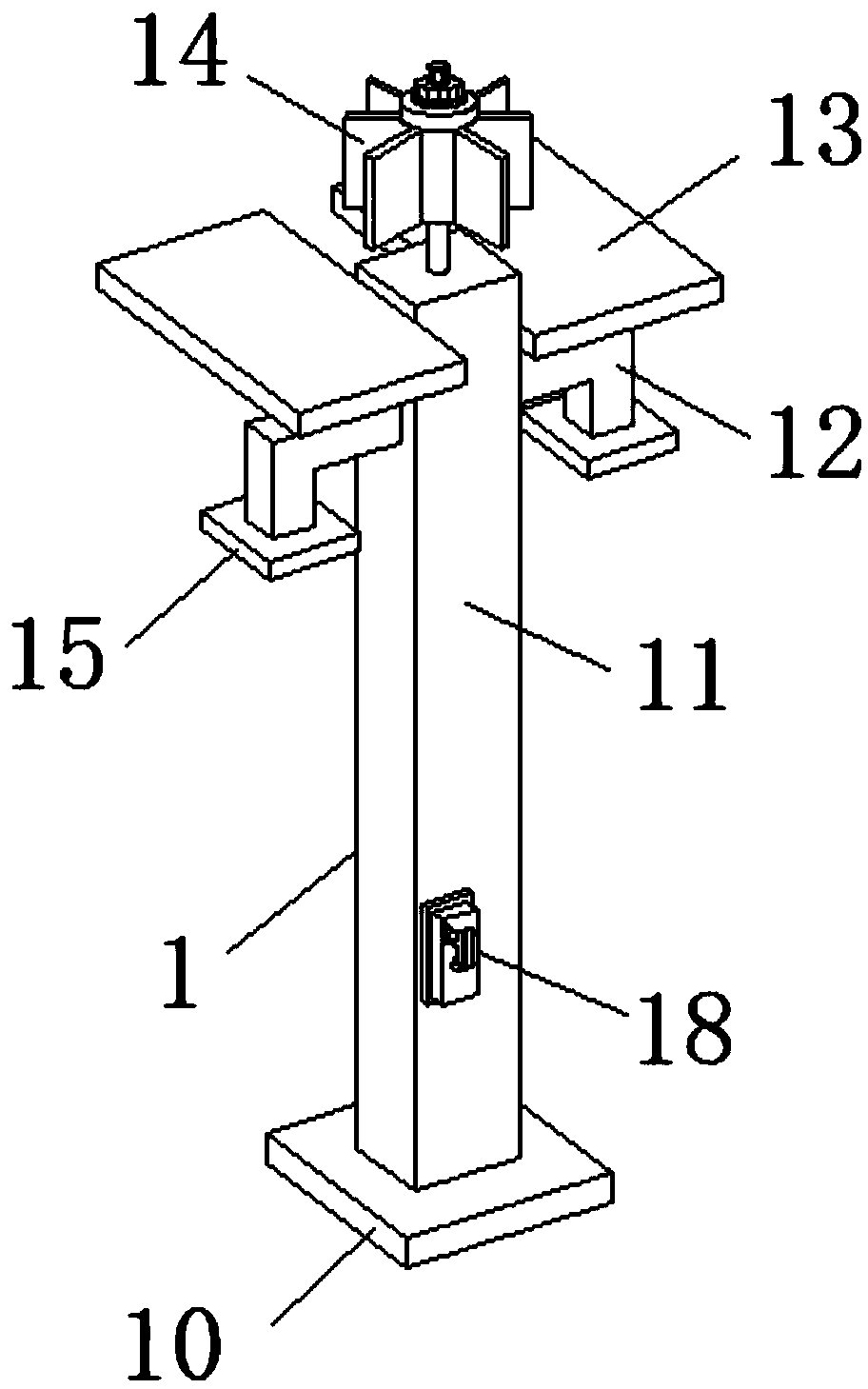
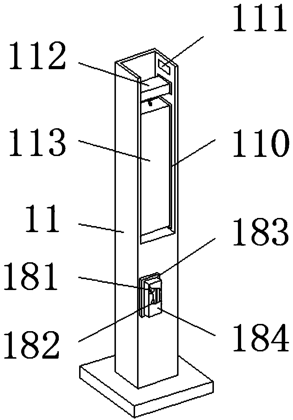
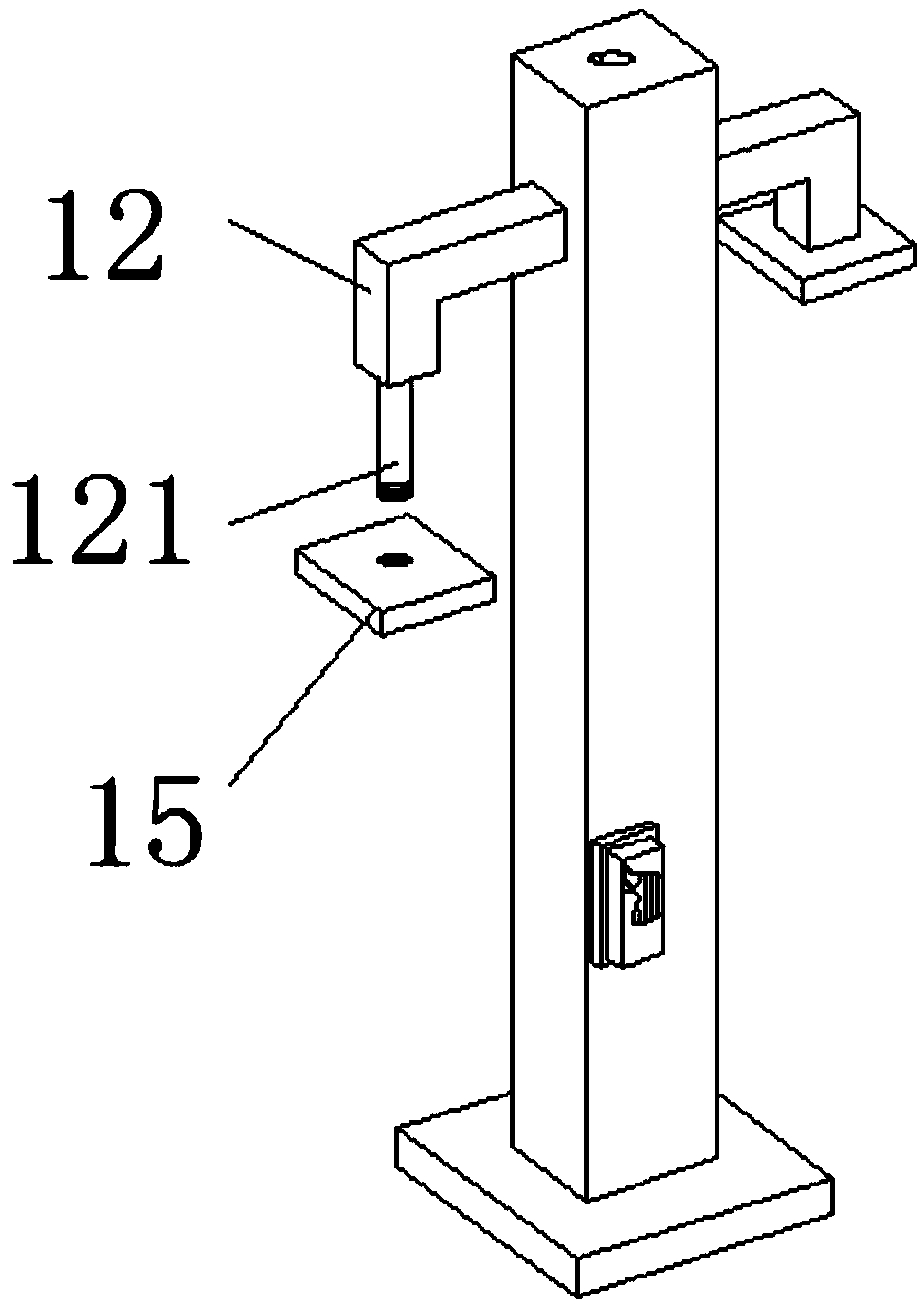
[0039] see Figure 1-7 , the present invention provides the following technical solutions: a new energy-saving and environment-friendly park lighting lamp, including a park lighting lamp 1, a base 10, a lighting lamp post 11, a mounting pillar 12, a solar power generation device 13, a wind power generator 14, and a lighting device 15 , wind speed sensor 16, light intensity sensor 17 and control device 18, park lighting lamp 1 includes base 10, lighting lamp post 11, installation pillar 12, solar power generation device 13, wind power generator 14, lighting device 15, wind speed sensor 16, light Intensity sensor 17 and control device 18, wherein, the top of base 10 is provided with lighting lamp column 11, and the upper part of lighting lamp post 11 is provided with installation pillar 12, and the lower part of illumination lamp column 11 is provided with control device 18, and the installation pillar 12 are provided with two in total, and the side of the two installation pilla...


PUM


Abstract

The invention discloses a new energy energy-saving and environment-friendly park illuminating lamp. The illuminating lamp is provided with an air velocity transducer and a light strength transducer which are used for monitoring the air velocity and light strength in a park correspondingly in real time. When the air velocity in the park is greater than a set value of the air velocity transducer andthe light strength is smaller than a set value of the light strength transducer, a controller controls a wind driven generator to work and store power preferentially; when the air velocity in the park is smaller than the set value of the air velocity transducer and the light strength is greater than the set value of the light strength transducer, the controller controls a solar generating deviceto work and store power preferentially; and when the air velocity and light strength in the park are simultaneously greater than the set values of the air velocity transducer and the light strength transducer, the controller controls the wind driven generator and the solar generating device to work and store power simultaneously. Due to the structure, the most appropriate power storage mode can beselected according to actual weather conditions, power storage work of the park illuminating lamp is better facilitated, and energy saving and environment friendliness are achieved.

Description

technical field [0001] The invention belongs to the technical field of lighting lamps, and in particular relates to a new energy-saving and environment-friendly park lighting lamp. Background technique [0002] Parks are an indispensable and important part of the urban construction system. They can improve the urban environment, provide urban residents with a good place to rest and entertain, and can also meet people's expectations of returning to nature. Lighting is also an important part of the park. One, although the function of existing park lights is improving day by day, there are still some deficiencies to be improved. [0003] The existing park lighting lamps have the following problems: 1. In order to avoid a large amount of waste of electric energy, the country has begun to advocate the use of energy-saving and environmentally friendly park lighting lamps. The other type is solar power generation lighting. Although both kinds of lighting can avoid excessive waste ...

Claims


Application Information

Patent Timeline
Patent Type & Authority Applications(China)
IPC IPC(8): F21S9/03F21S9/04F21V21/02F21V21/10F21V23/04F21V23/00F21V19/00F21V21/36
CPCF21S9/035F21S9/043F21V19/001F21V21/02F21V21/10F21V21/36F21V23/003F21V23/0442
Inventor 韦华宁
Owner 肇庆中能创智信息科技有限公司
Why Eureka
Try Eureka