
An expander unit and a pulse-tube type free-piston Stirling refrigerator

A technology for expanders and refrigerators, applied in refrigerators, gas cycle refrigerators, refrigeration and liquefaction, etc., can solve the problems of low efficiency and dissipation of pulse tube refrigerators, eliminate pumping gas losses, and reduce the size of the whole machine Quality, the effect of reducing manufacturing difficulty

Active Publication Date: 2019-12-31
UNIV OF SHANGHAI FOR SCI & TECH
View PDF5 Cites 0 Cited by
  • Summary
  • Abstract
  • Description
  • Claims
  • Application Information

AI Technical Summary

Problems solved by technology

[0005] The reason why the efficiency of the pulse tube refrigerator is lower than that of the Stirling refrigerator is mainly because the pulse tube refrigerator does not have a structure such as the expansion piston of the Stirling refrigerator, which "feeds back" the expansion work of the gas to the compression chamber. The expansion work of the hot end is mainly dissipated to the environment in the form of heat through phase-modulating mechanisms such as inertial tubes and small holes, resulting in low efficiency of pulse tube refrigerators

Method used


Image

  • An expander unit and a pulse-tube type free-piston Stirling refrigerator
  • An expander unit and a pulse-tube type free-piston Stirling refrigerator
  • An expander unit and a pulse-tube type free-piston Stirling refrigerator

Examples


Embodiment 1

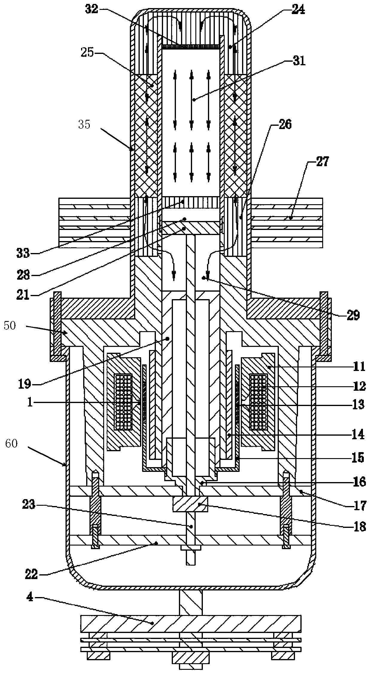
[0030] Such as figure 1 As shown, the coaxial pulse tube type free-piston Stirling refrigerator 100 includes a linear motor 1 , a compression unit, an expander unit, an undamped dynamic vibration absorption unit 4 , a frame 50 , and a casing 60 .

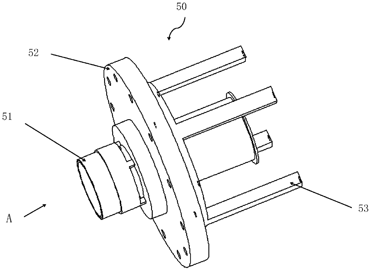
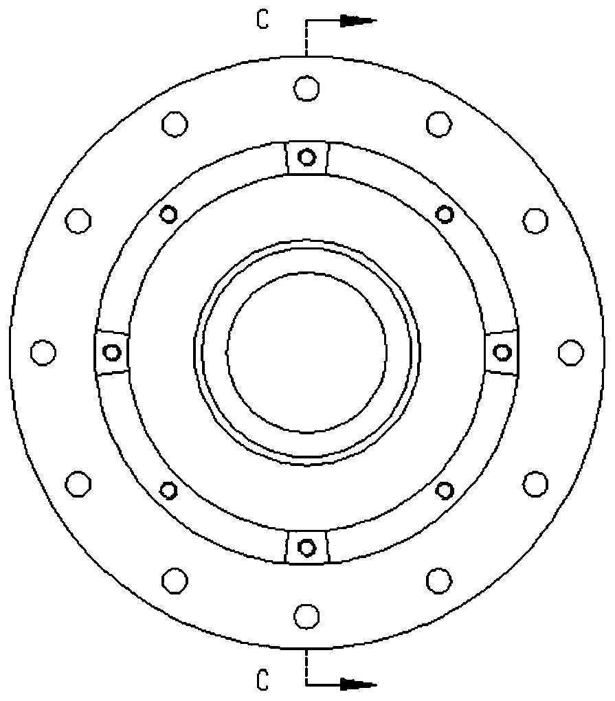
[0031] Such as figure 2 , 3 , 4 and 5, the frame 50 includes a flange 52, a piston tube 51 and a base 53 arranged in the flange 52,

[0032] Wherein, the flange 52 is in the shape of a disk, and a concentric small disk 521 is arranged on one side of the flange, and a plurality of connecting through holes are uniformly arranged on the flange 52 .

[0033] The base 53 is cylindrical, one end is connected to one side of the flange 52, and the other end is a free end. The centerline of the base 53 coincides with the centerline of the flange 52, and the free end of the base 53 is provided with a plurality of connecting screw holes. In an embodiment, the base 53 is four legs arranged around the centerline of the flange 52 .

[0034] ...

Embodiment 2

[0059] The other structure of this embodiment is the same as that of Embodiment 1, except that it also includes a radiator 27 located on the outside of the first-stage hot-end heat exchanger 26 and arranged on the shell, and the first-stage hot-end heat exchanger 26 passes heat through the outer shell Passed to the radiator 27 on the outside, finally released to the environment.

Embodiment 3

[0061] The other structure of this embodiment is the same as that of the second embodiment, except that it also includes a deflector 32 arranged at one end of the pulse tube and located inside the pulse tube, and the deflector 32 is connected with the cold end heat exchanger 24 .


PUM


Abstract

The invention provides an expansion machine unit and a pulse tube type free piston stirling refrigerator. The pulse tube type free piston stirling refrigerating machine comprises a linear motor, a compression unit, an expansion machine unit, a non-damping power vibration absorbing unit, a machine frame and a shell, wherein the expansion machine unit is arranged on the machine frame and comprises an expansion piston, an expansion piston spring, an expansion piston rod, a primary hot end heat exchanger, a secondary hot end heat exchanger, a heat regenerator, a pulse tube and a cold end heat exchanger; and the machine frame comprises a flange, a piston tube and a base, wherein the piston tube and the base are arranged in the flange, the expansion piston is arranged in the piston tube, the expansion piston spring is fixedly connected with the machine frame through a connecting part, one end of the expansion piston rod is connected with the expansion piston, the other end of the compressionpiston is connected with the expansion piston spring, and the compression piston, the expansion piston and a piston cavity form a compression cavity.

Description

technical field [0001] The invention belongs to the refrigeration field, and in particular relates to an expander unit and a pulse-tube type free-piston Stirling refrigerator. Background technique [0002] As an important method to obtain low temperature, cryogenic refrigerator refrigeration is widely used in the fields of aviation, military, superconductivity, communication, electronics, metallurgy, industrial gas liquefaction, and biomedicine. Especially in recent years, the demand for the application of cryogenic refrigerators in refrigerators, wine cabinets, etc. is increasing. [0003] The theoretical refrigeration efficiency of the Stirling refrigerator is equal to the Carnot efficiency, and its actual operating efficiency is also the most efficient among all cryogenic refrigerators at present. The structure of the free-piston Stirling refrigerator was proposed by William Beale in the 1960s. Its main features are the use of linear compressor drive, flexible spring sup...

Claims


Application Information

Patent Timeline
Patent Type & Authority Patents(China)
IPC IPC(8): F25B9/14
CPCF25B9/145F25B2309/1412
Inventor 陈曦张利锦
Owner UNIV OF SHANGHAI FOR SCI & TECH
Learn More