
Device for measuring arm length difference of fiber optic interferometer

A technology of optical fiber interferometer and measuring device, which is applied in the direction of measuring device, optical instrument testing, machine/structural component testing, etc. And the effect of measurement accuracy, measurement operation is simple and easy

Pending Publication Date: 2018-11-16
苏州维创度信息科技有限公司
View PDF0 Cites 22 Cited by
  • Summary
  • Abstract
  • Description
  • Claims
  • Application Information

AI Technical Summary

Problems solved by technology

[0003] At present, there are mainly white light interferometry, coherent light interference fringe counting method and microwave photon mixing method to measure the length difference between the two arms of the fiber optic interferometer. The precise measurement of the signal light introduces the optical path difference between the two arms of the interferometer, and the arm length difference is obtained after conversion, but it is limited by the scanning range of the scanning table, and the length of the measurable arm length difference is relatively short; coherent The optical interference fringe counting method measures the arm length difference by observing the interference fringe spacing, which is relatively difficult to implement; the microwave photon mixing method modulates the arm length difference signal to the phase of the light-borne microwave, and demodulates the phase to measure the arm length difference, which can achieve a relatively High-precision measurement, but its structure is complicated and the cost is high

Method used


Image

  • Device for measuring arm length difference of fiber optic interferometer
  • Device for measuring arm length difference of fiber optic interferometer
  • Device for measuring arm length difference of fiber optic interferometer

Examples


Embodiment Construction

[0030] The present invention will be further explained below in conjunction with the accompanying drawings and specific embodiments. It should be understood that the following specific embodiments are only used to illustrate the present invention and are not intended to limit the scope of the present invention.

[0031] A method for measuring the arm length difference of an optical fiber interferometer. Interference is performed in the microwave domain through a dual optical frequency comb, and a spectrum analyzer is used to measure the interference signal. The arm length of the optical fiber interferometer to be measured can be obtained through the bandwidth of the interference signal within one cycle. Difference.

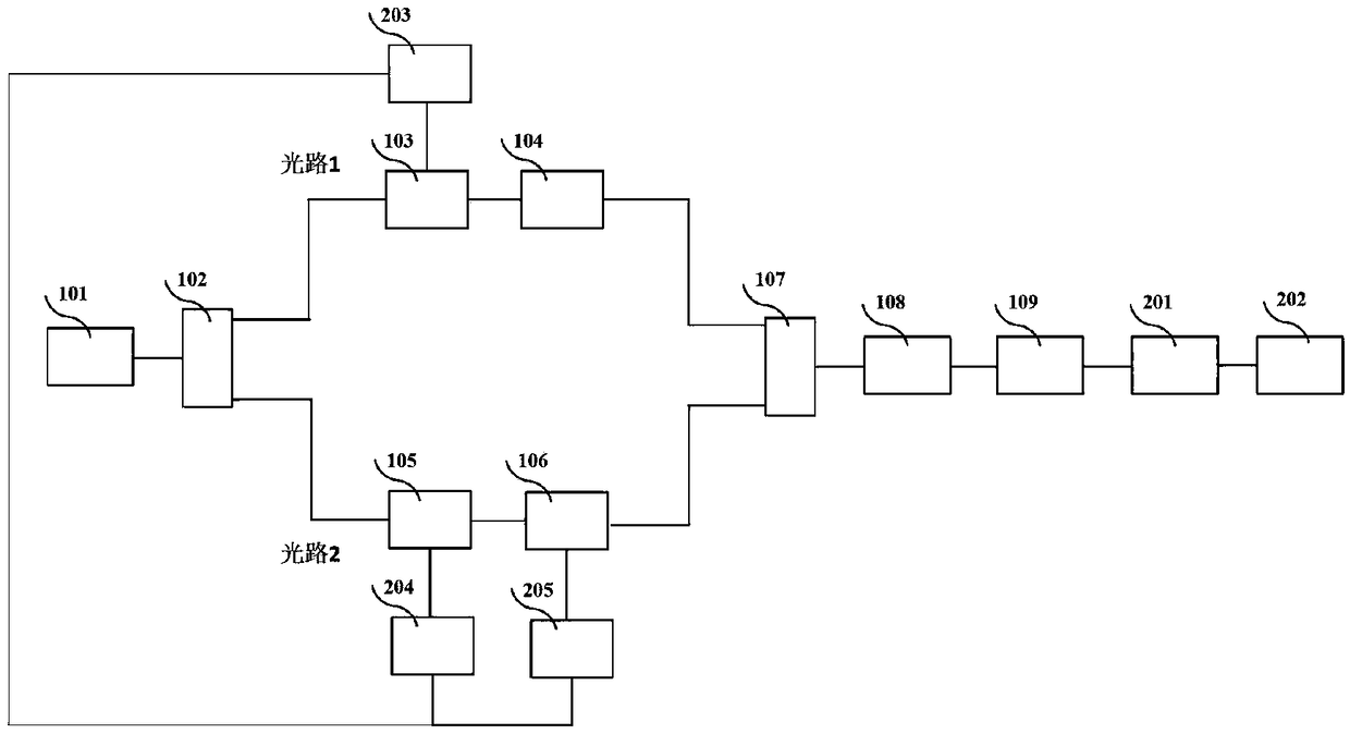
[0032] Such as figure 1 As shown, the measuring device for the arm length difference of an optical fiber interferometer includes a narrow linewidth laser 101, a polarization maintaining fiber coupler 102, a phase modulator 103, a polarization state controller 104,...


PUM


Abstract

The invention relates to a device for measuring the arm length difference of a fiber optic interferometer, and mainly solves a problem that a measurement system employing an optical interference method is not high in stability and is low in measurement precision. The device provided by the invention comprises a narrow linewidth laser, a polarization-maintaining fiber coupler, a phase modulator, apolarization state controller, an acousto-optic frequency shifter, a fiber coupler, a to-be-tested fiber optic interferometer, a photoelectric detector, a frequency spectrograph, a signal processing and display module and a microwave signal generator. The device carries out the interference in microwave domain through a double optical frequency comb, and measures an interference signal by using the frequency spectrograph. The device can obtain the arm length difference of the to-be-tested fiber optic interferometer by the bandwidth of the interference signal in one cycle, and can achieve the measurement of the precision changes through changing the frequency interval of the optical frequency comb, thereby improving the measurement accuracy and the stability of the system, and ironing out the defect that a method employing optical interference cannot achieve the measurement of the arm length difference. The device is simple in workflow is simple and is high in generalizability.

Description

technical field [0001] The invention relates to a device for testing and measuring the performance of an optical fiber sensor, in particular to a device for measuring the arm length difference of an optical fiber interferometer. Background technique [0002] Due to its excellent performance, fiber optic interferometer has been widely used in the fields of fiber optic temperature, vibration sensing, fiber optic hydrophone and quantum key communication. The length difference between the two arms of the interferometer directly determines the measurement sensitivity and communication speed of the above-mentioned measurement and communication system. With the rapid development of contemporary communication technology and sensor measurement technology, it is of great significance to accurately measure the difference in the length of the two arms of the interferometer. [0003] At present, there are mainly white light interferometry, coherent light interference fringe counting meth...

Claims


Application Information

Patent Timeline
IPC IPC(8): G01M11/02
CPCG01M11/30G01M11/0271
Inventor 周欢生
Owner 苏州维创度信息科技有限公司
Learn More