
Device and method for measuring electromagnetic parameter of material in microwave heating process

An electromagnetic parameter and microwave heating technology, which is applied in the direction of measuring device, magnetic property measurement, dielectric property measurement, etc., can solve the problems that cannot be used to measure the electromagnetic parameters of materials, etc.

Active Publication Date: 2018-11-16
NANJING UNIV OF AERONAUTICS & ASTRONAUTICS
View PDF7 Cites 11 Cited by
  • Summary
  • Abstract
  • Description
  • Claims
  • Application Information

AI Technical Summary

Problems solved by technology

[0005] The object of the present invention is to solve the problem that the existing electromagnetic parameter measuring device cannot be used to measure the electromagnetic parameter of the material in the microwave heating process, and to invent a material electromagnetic parameter measuring device in the microwave heating process, so as to realize the measurement of the material electromagnetic parameter in the microwave heating process. effective measurement, and at the same time provide a corresponding alternate measurement method of electromagnetic parameters

Method used


Image

  • Device and method for measuring electromagnetic parameter of material in microwave heating process
  • Device and method for measuring electromagnetic parameter of material in microwave heating process
  • Device and method for measuring electromagnetic parameter of material in microwave heating process

Examples


Embodiment 1

[0031] Such as Figure 1-3 As shown.

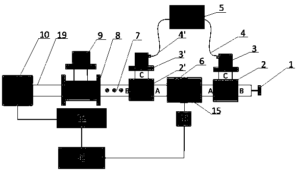
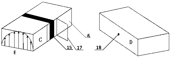
[0032] A device for measuring electromagnetic parameters of materials in a microwave heating process, the device includes a microwave heating system and an electromagnetic parameter measuring system; the microwave heating system includes a microwave single-mode resonant cavity 6 and a microwave source 10, the microwave single-mode resonant cavity 6 The two ends are respectively connected to the A terminal of the first waveguide switch 2' and the second waveguide switch 2, the B terminal of the first waveguide switch 2' is connected to the adapter 7, the adapter 7 is connected to the circulator 8, and the circulator 8 is connected to the The water load 9 is connected to the microwave source 10 through the waveguide transmission line 19 on the other hand; the B terminal of the second waveguide switch 2 is connected to the terminal adapter 1, and the material 15 is placed in the microwave single-mode resonant cavity 6 for microwave heating; ...

Embodiment 3

[0043] Measurement of electromagnetic parameters of epoxy resin during microwave heating. The first waveguide switch 2' and the second waveguide switch 2 adopt an electromagnetic control method. Use the following steps to test the electromagnetic parameters of epoxy resin during microwave heating,

[0044] The first step is to adjust the first waveguide switch 2' and the second waveguide switch 2 so that the A terminal and the C terminal are connected, and the remaining ports are short-circuited to form an electromagnetic parameter measurement system, and the entire electromagnetic parameter measurement system is calibrated;

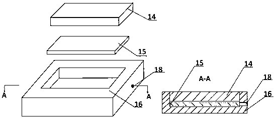
[0045] In the second step, epoxy resin 15 is poured into the groove 16 of the sample holder and sealed with a cover plate 14 . The sample fixture is made of high temperature-resistant and wave-transparent polytetrafluoroethylene, and the outer dimension is 86 (length) × 43 (width) × 20 (thickness) mm 3 , the internal groove size is 80 (length) × 38 (wi...


PUM


Abstract

The invention relates to a device and method for measuring the electromagnetic parameter of a material in a microwave heating process. According to the device and method, a waveguide switch is adoptedto realize the controllability of the separation of a microwave heating system from an electromagnetic parameter measuring system; a microwave heating process and a microwave heating process are alternately performed so as to measure the electromagnetic parameter of the material during the entire microwave heating process. The device and method of the invention are simple and highly feasible. With the device and method adopted, a foundation can be laid for the analysis and adjustment of the microwave heating process of the material.

Description

technical field [0001] The invention relates to an electromagnetic parameter measuring device, in particular to an electromagnetic parameter measuring device for materials in a microwave heating process. Background technique [0002] Microwaves are electromagnetic waves with a frequency of 300M to 300GHz. Microwave heating is a heating method in which materials rely on absorbing microwave energy and converting it into heat energy, so that the entire material is heated up at the same time. The electromagnetic parameters of the material directly determine the absorbing performance of the material. However, the phase transition reaction or molecular thermal motion of the material during the heating process will greatly affect the electromagnetic parameters of the material. Therefore, measuring the electromagnetic parameters of materials throughout the microwave heating process is crucial for analyzing and adjusting the microwave heating process. [0003] In the existing meth...

Claims


Application Information

Patent Timeline
Patent Type & Authority Applications(China)
IPC IPC(8): G01R31/00G01R27/26G01R33/12
CPCG01R27/2694G01R31/00G01R33/12G01R33/1223
Inventor 李迎光周靖张梦宸
Owner NANJING UNIV OF AERONAUTICS & ASTRONAUTICS
Learn More