
Rotor ironless permanent magnet synchronous motor

A permanent magnet synchronous and motor technology, applied in the field of motors, can solve the problems of high mechanical loss permanent magnet consumption, magnetic permeability difference reluctance, high magnet usage, etc. effect of life

Inactive Publication Date: 2018-11-16
武汉麦迪嘉机电科技有限公司
View PDF3 Cites 2 Cited by
  • Summary
  • Abstract
  • Description
  • Claims
  • Application Information

AI Technical Summary

Problems solved by technology

[0003] At present, in order to save energy and reduce emissions, a large number of permanent magnet motors have been put into use in accordance with the relevant national requirements for the improvement of motor energy efficiency, and the energy saving effect is better. The existing permanent magnet motors are mainly improved on the basis of asynchronous motors, and the motor rotor is added The permanent magnet rotor realizes the non-electric excitation of the permanent magnet motor and improves the efficiency of the motor, but there are still problems such as a large amount of iron loss, mechanical loss and the amount of permanent magnets. Iron-free, eliminating magnetic damping and iron loss, the efficiency has been greatly improved compared to ordinary permanent magnet motors, but in complex production processes, poor magnetic permeability, high magnetic resistance, high magnet usage, high production costs and limited use Small power generators and motors

Method used


Image

  • Rotor ironless permanent magnet synchronous motor
  • Rotor ironless permanent magnet synchronous motor

Examples


Embodiment Construction

[0023] The following will clearly and completely describe the technical solutions in the embodiments of the present invention with reference to the accompanying drawings in the embodiments of the present invention. Obviously, the described embodiments are only some, not all, embodiments of the present invention. Based on the embodiments of the present invention, all other embodiments obtained by persons of ordinary skill in the art without making creative efforts belong to the protection scope of the present invention.

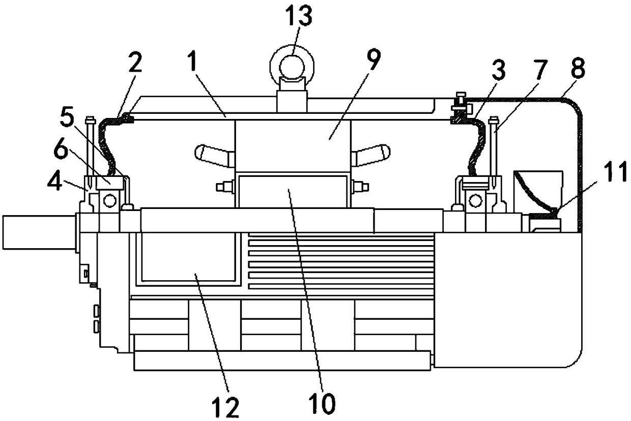
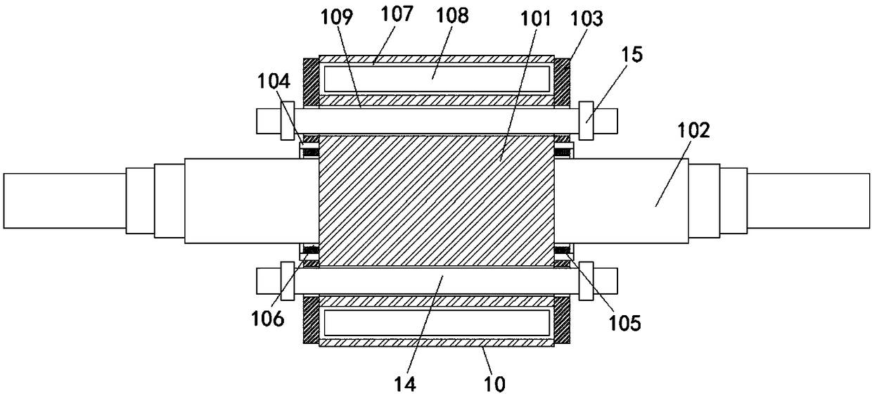
[0024] see Figure 1-2, the rotor ironless permanent magnet synchronous motor, including the motor housing 1, through the motor housing 1 of the device, the use of polymer materials with good magnetic conductivity can reduce the volume of the motor, and there is no iron in the rotor 10, which can save 50% per unit compared with traditional permanent magnet motors The above silicon steel sheets play a role in saving resources, resulting in light material of the...


PUM


Abstract

The invention relates to the technical field of motors, and discloses a rotor ironless permanent magnet synchronous motor, which comprises a motor outer shell, wherein a front end cover is fixedly mounted on the left side of the motor outer shell, a rear end cover is fixedly mounted on the right side of the motor outer shell, the left side of the front end cover and the right side of the rear endcover are each fixedly provided with a bearing outer cover, the left side of the front end cover and the left side of the rear end cover are each fixedly provided with a bearing inner cover, bearingsare fixedly mounted in the interior of the front end cover and the interior of the rear end cover, oil inlet pipes are fixedly mounted in the interior of the two bearing outer covers, a wind cover isfixedly mounted on the right side of the rear end cover, a stator is are fixedly mounted on the inner surface of the motor outer shell, and the inner surface of the stator is movably connected with arotor. The rotor ironless permanent magnet synchronous motor adopts a polymer material to replace silicon steel sheets and other ferrous magnetic conductive materials, realizes ironless permanent magnetization, has no iron loss and high magnet usage rate, and reduces the magnet usage amount.

Description

technical field [0001] The invention relates to the technical field of motors, in particular to a rotor ironless permanent magnet synchronous motor. Background technique [0002] The motor is a device that converts electrical energy into mechanical energy. It uses a energized coil to generate a rotating magnetic field and acts on the rotor to form a magnetoelectric force. The motor is divided into DC motors and AC motors according to the power supply used. The motors in the power system are large Part of it is an AC motor, which can be a synchronous motor or an asynchronous motor. The motor is mainly composed of a stator and a rotor. The direction of the energized wire in the magnetic field is related to the direction of the current and the direction of the magnetic induction line. The working principle of the motor is that the magnetic field affects the current. The action of force makes the motor rotate. [0003] At present, in order to save energy and reduce emissions, a...

Claims


Application Information

Patent Timeline
IPC IPC(8): H02K21/14H02K1/27
Inventor 罗贵波韩宏
Owner 武汉麦迪嘉机电科技有限公司
Learn More