Die combination structure
A mold combination and mold technology, applied in the direction of manufacturing tools, other manufacturing equipment/tools, etc., can solve the problems of crushing of die-cutting products, inability to clear the debris in the knife cavity, and low precision.
- Summary
- Abstract
- Description
- Claims
- Application Information
AI Technical Summary
Problems solved by technology
Method used
Image

Examples
Embodiment Construction
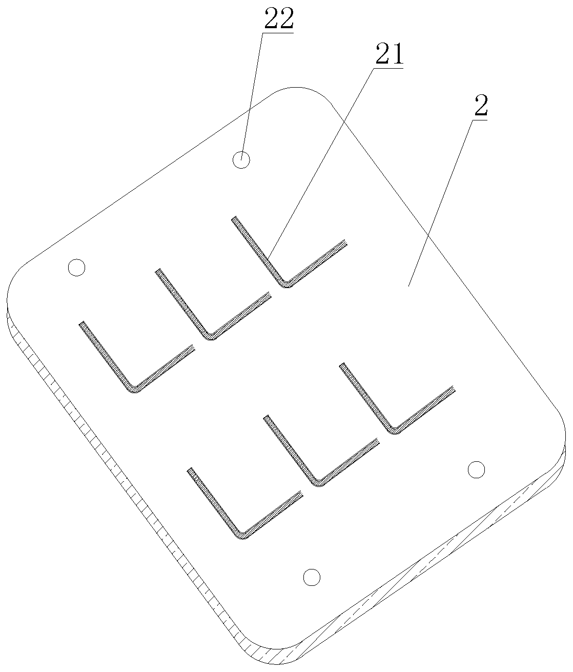
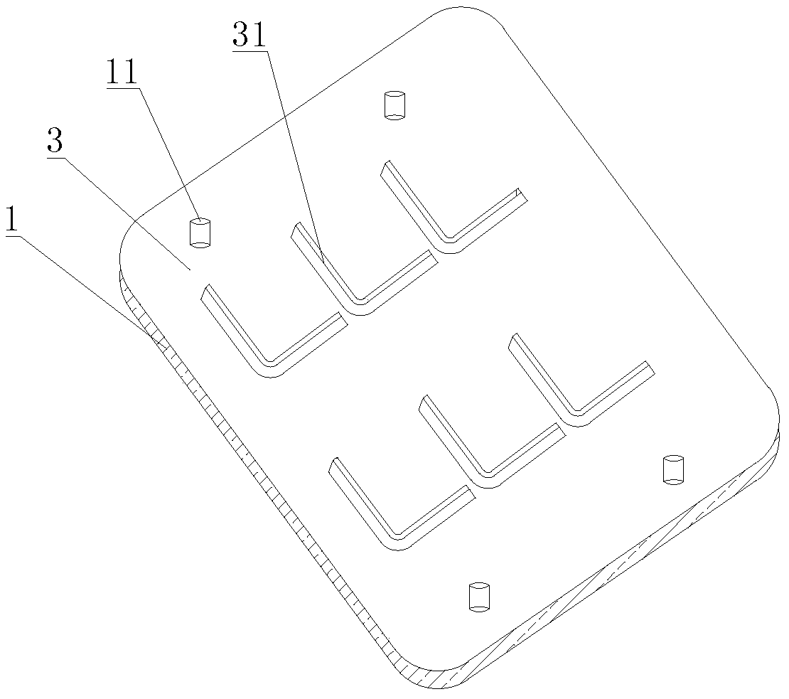
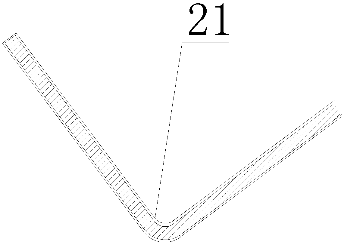
[0020] See figure 2 Shown, a kind of mold assembly structure, it comprises cutting die mold, and cutting die mold comprises upper cutting die mold (not drawn in the figure) and lower cutting die mold 1, and cutting die mold is installed on the die-cutting machine (not drawing in the figure) out), a milling cutter (not shown in the figure) is installed on the die-cutting machine, and the milling cutter is set correspondingly to the cutting die. 1 matches the shape of the die-cut product 31, which also includes a slow wire cutting mold 2, such as figure 1 , image 3 As shown, the slow wire cutting mold 2 is provided with several evenly arranged slow wire slotted holes 21 corresponding to the outline of the die-cut product 31, and the shape of the die-cut product 31 in this embodiment is an L with arc-shaped corners. shape, so the shape of the slow wire threading slot hole 21 is set to L shape, the corner of the L-shaped slow thread threading slot hole 21 is arc-shaped, and th...
PUM
| Property | Measurement | Unit |
|---|---|---|
| Radius | aaaaa | aaaaa |
| Arc angle | aaaaa | aaaaa |
| Thickness | aaaaa | aaaaa |
Abstract
Description
Claims
Application Information
PatSnap Eureka turns technology decisions into work you can execute. Powered by our Innovation Knowledge Graph, it runs expert workflows across engineering, life sciences, materials and intellectual property. Get your review-ready output in minutes.


