Laser machining and locating method

A technology of laser processing and positioning method, applied in laser welding equipment, metal processing equipment, manufacturing tools, etc., can solve the problem of poor positioning accuracy, and achieve the effect of improving accuracy and quality, easy to implement, and strong anti-interference ability

Active Publication Date: 2018-11-20
CIVIL AVIATION UNIV OF CHINA
View PDF9 Cites 0 Cited by
  • Summary
  • Abstract
  • Description
  • Claims
  • Application Information

AI Technical Summary

Problems solved by technology

[0004] In order to solve the above problems, the purpose of the present invention is to provide a laser processing positioning method, which overcomes the shortcomings of poor positioning accuracy of relying on visible light in the trad

Method used


Image

  • Laser machining and locating method
  • Laser machining and locating method

Examples


Example Embodiment

[0015] The technical solutions in the embodiments of the present invention will be described clearly and completely in conjunction with the drawings in the embodiments of the present invention. Obviously, the described implementation examples are only part of the implementation examples of the present invention, rather than all implementation examples. Based on the implementation examples in the present invention, all other implementation examples obtained by those of ordinary skill in the art without creative work shall fall within the protection scope of the present invention.

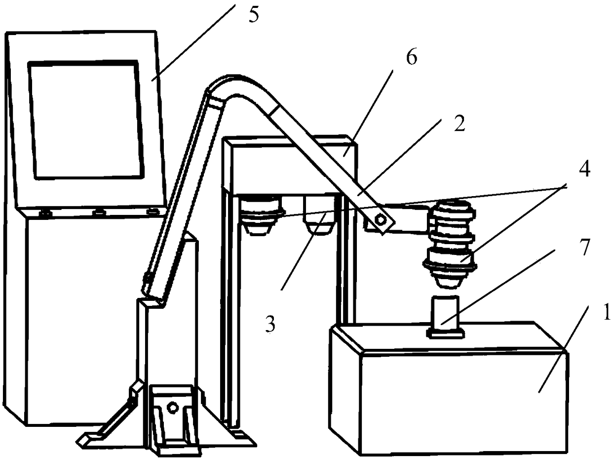
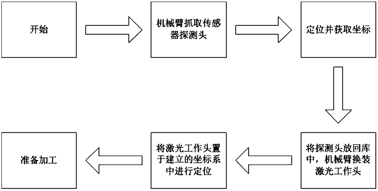
[0016] Such as figure 1 As shown, the laser processing positioning method provided by the present invention includes the following steps in sequence:

[0017] 1) Construct a laser processing positioning system, which includes a workbench 1, a mechanical arm 2, a probe with a sensor 3, a laser processing work head 4, a computer control system 5, and a tool library 6; the lower end of the workbench 1 is pla...


PUM


Abstract

The invention provides a laser machining and locating method. The method comprises the steps that a laser machining and locating system is constructed; a mechanical arm grabs a detection head and installs the detection head at the tail end of the mechanical arm; a computer control system and the detection head are utilized for carrying out initialized location on blades of an aviation engine, andlocating coordinate data are obtained; the mechanical arm grabs a laser machining work head and installs the laser machining work head at the tail end of the mechanical arm, the computer control system and the locating coordinate data are utilized for converting the laser machining work head into a coordinate system determined by the locating coordinate data, and then laser emitted by the laser machining work head begins to be utilized for carrying out machining. The method has the effects that by means of location of a sensor controlled by a computer, three-dimensional coordinate modeling canbe carried out in the laser machining process, the computer is utilized for dealing with and converting coordinates to locate the machined blades of the aviation engine, thus the defects that duringtraditional laser machining, locating stability of visible light is poor, and precision is low can be overcome, meanwhile, the disturbance resisting ability of sensor location is high, and combinationwith the laser machining technology can be well achieved.

Description

technical field [0001] The invention belongs to the technical field of digitized manufacturing and repair of aero-engine components, and in particular relates to a laser processing positioning method. Background technique [0002] With the rapid development of my country's aerospace and national defense industries, the strategic position of aero-engines is getting higher and higher, so higher requirements are put forward for the precision of manufacturing or repairing aero-engine blades. Laser processing technology has been widely used in digital manufacturing and repair of aero-engine components due to its advantages of heat concentration, fast heating and cooling, and small heat-affected zone. The accuracy of laser machining positioning is a major guarantee for the machining accuracy and repair quality of aeroengine blades. Traditional laser machining positioning relies on visible light positioning, and the accuracy is not high, which seriously restricts the development of...

Claims


Application Information

Patent Timeline
IPC IPC(8): B23K26/00B23K26/70
CPCB23K26/00B23K26/70B23K26/702
Inventor 王涛王盛乔伟林李战
Owner CIVIL AVIATION UNIV OF CHINA
Why Eureka
Try Eureka