
Automobile part machining device

A technology for auto parts and processing devices, applied in the field of auto parts processing, can solve problems such as affecting processing efficiency, and achieve the effects of long service life, increased contact area, and uniform force

Pending Publication Date: 2018-11-20
重庆炅达贸易有限公司
View PDF0 Cites 2 Cited by
  • Summary
  • Abstract
  • Description
  • Claims
  • Application Information

AI Technical Summary

Problems solved by technology

[0003] The present invention intends to provide a processing device for auto parts to solve the problem that the existing tooling can only clamp a single brake pad for processing, which affects the processing efficiency

Method used


Image

  • Automobile part machining device

Examples


Embodiment Construction

[0013] The following is further described in detail through specific implementation methods:

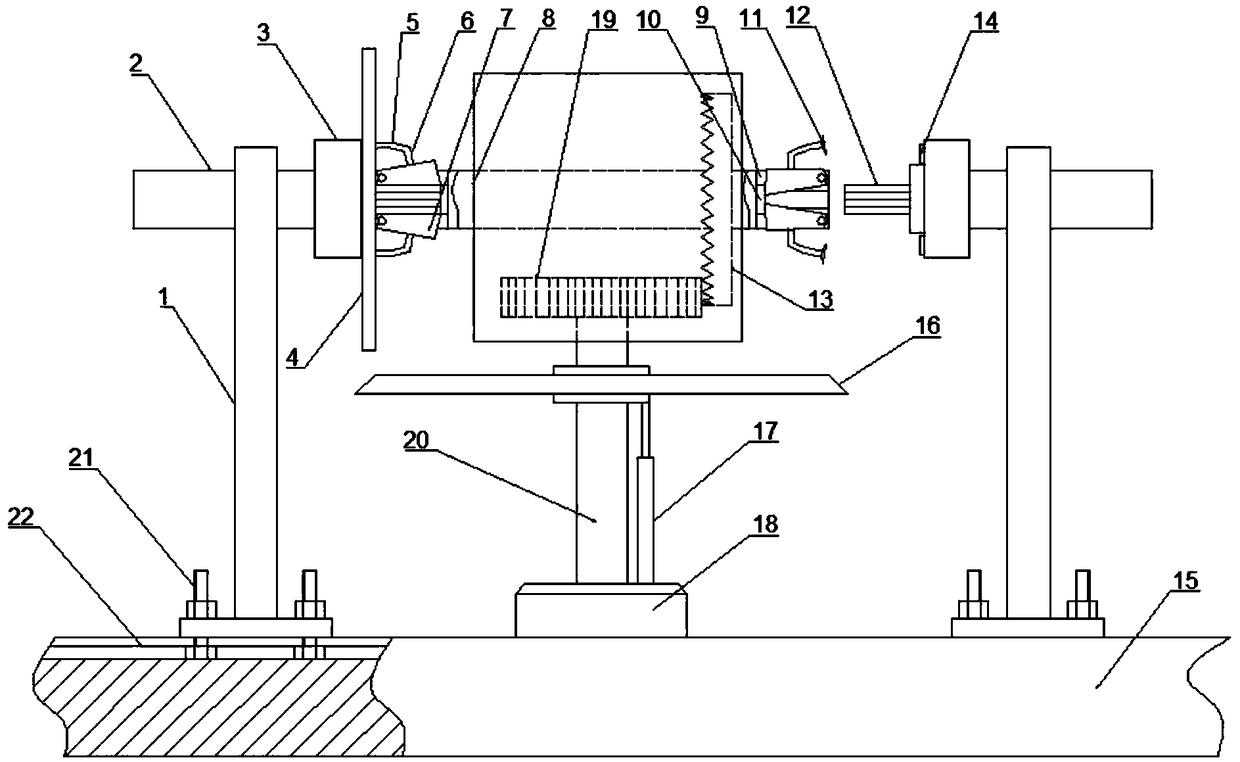
[0014] The reference signs in the drawings of the specification include: bracket 1, support shaft 2, positioning platform 3, brake pad 4, positioning claw 5, connecting rod 6, wedge 7, spacer shaft 8, keyway 9, positioning groove 10, suction cup 11 , spline table 12, gear plate 13, rubber ring 14, base 15, grinding wheel 16, hydraulic telescopic rod 17, motor 18, gear 19, rotating shaft 20, positioning bolt 21, T-shaped groove 22.

[0015] The embodiment is basically as attached figure 1 As shown: the auto parts processing device, including a base 15, the middle part of the base 15 is provided with a mounting groove, and a motor 18 with the output end facing upward is installed in the mounting groove through bolts, and the rotating shaft 20 of the motor 18 is crimped sequentially through bolts from bottom to top Grinding wheel 16 is arranged and connecting seat is installed by beari...


PUM


Abstract

The invention discloses an automobile part machining device in the field of automobile part machining. The automobile part machining device comprises a base, wherein a mounting groove is formed in themiddle of the base, and a motor with an upward output end is installed in the mounting groove; a grinding wheel and a connecting base are sequentially connected to a rotating shaft of the motor frombottom to top, and a transverse spacing shaft is rotationally connected to the connecting base; two supports are slidably connected to the base, the two supports are symmetrically distributed on the left side and the right side of the motor, a supporting shaft is rotationally connected to the top end of each support, and a clamping base is arranged on the portion, facing the end of the motor, of each supporting shaft; and each end part of the spacing shaft is provided with a clamping head, and each clamping base is detachably connected with the corresponding clamping head. According to the automobile part machining device, two brake pads can be chamfered at the same time through one grinding wheel, so that the machining efficiency is high, and the problem that the machining efficiency is affected due to the fact that an existing tool can only clamp one brake pad for machining is solved.

Description

technical field [0001] The invention relates to the field of auto parts processing, in particular to an auto parts processing device. Background technique [0002] In the braking system of a car, the brake pad is the most critical safety part, and the quality of the brake pad determines the braking effect and safety performance of the car. The brake pads will cause wear to the brake disc during long-term use, especially the edge of the brake pad. Therefore, it is necessary to chamfer the edge of the brake pad during the production process to prevent the friction between the brake pad and the brake disc from causing noise or even wear out. At present, the tooling used when processing and chamfering the brake pads can only clamp a single brake pad for processing, which makes the processing efficiency of the brake pads low. Contents of the invention [0003] The invention intends to provide a processing device for auto parts to solve the problem that the existing tooling ca...

Claims


Application Information

Patent Timeline
IPC IPC(8): B24B9/00B24B41/06B24B47/12B24B47/20
CPCB24B9/00B24B41/06B24B47/12B24B47/20
Inventor 姚竹清
Owner 重庆炅达贸易有限公司
Learn More