Surrounding and protecting structure with outer surface provided with resistance reducing device

A technology of enclosure structure and drag reducer, applied in mechanical equipment, machine/engine, installation/support configuration of wind turbines, etc., can solve problems such as easily affected construction period, hoisting progress, installation period limitation, etc.

Active Publication Date: 2018-11-20
BEIJING GOLDWIND SCI & CREATION WINDPOWER EQUIP CO LTD
View PDF5 Cites 7 Cited by
  • Summary
  • Abstract
  • Description
  • Claims
  • Application Information

AI Technical Summary

Problems solved by technology

It can be seen that the on-site hoisting progress and installation period are obviously limited by the local wind conditions

Method used


Image

  • Surrounding and protecting structure with outer surface provided with resistance reducing device
  • Surrounding and protecting structure with outer surface provided with resistance reducing device
  • Surrounding and protecting structure with outer surface provided with resistance reducing device

Examples


Embodiment Construction

[0045] In order to enable those skilled in the art to better understand the technical solutions of the present invention, the present invention will be further described in detail below in conjunction with the accompanying drawings and specific embodiments.

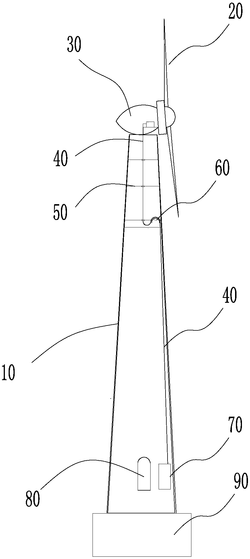
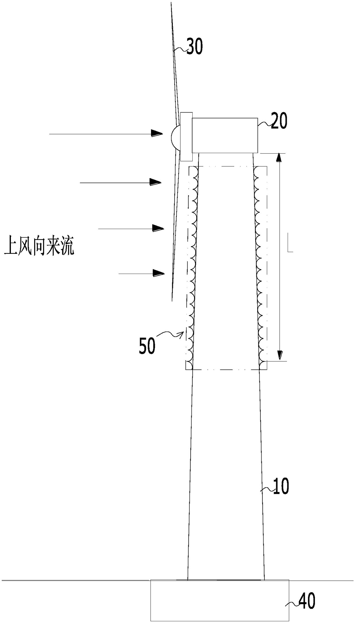
[0046] Please refer to figure 2 , figure 2 In the embodiment of the tower tube 10 provided by the present invention, a schematic structural diagram of a drag reducer is provided on its upper part.

[0047] This embodiment shows a specific enclosure structure, that is, a tower 10 , and the outer surface of the tower 10 is provided with a drag reducer 50 . refer to image 3 , the drag reducer 50 includes an annular groove 501 located on the outer surface of the tower 10, the cross section of the annular groove 501 ( figure 2 The middle is the cross section along the radial direction of the tower tube 10) is arc-shaped, and the tower tube 10 is provided with a drag reducer 50 in at least part of the height range, fig...


PUM

PropertyMeasurementUnit
Groove depthaaaaaaaaaa

Abstract

The invention discloses a surrounding and protecting structure with the outer surface provided with a resistance reducing device. The resistance reducing device comprises annular grooves which are formed in the outer surface of the surrounding and protecting structure in a surrounding manner in the circumferential direction. The sections of the annular groove are arc. A ridge-shaped annular rib isformed between the vertically-adjacent annular grooves. The annular rib comprises a rigid ridge back and an elastic cavity or solid elastic cavity or flexible cavity or solid flexible body below theridge back. The resistance reducing device comprises the annular rib. The resistance reducing device is arranged in at least part of the height range of the surrounding and protecting structure. An arc groove wall is used for conducting disordering guiding in the momentum direction of flow coming from the upward direction, and the resistance and amplitude in the following wind direction are reduced. The ridge back can be used for cutting the incoming flow sharply and dividing the incoming flow into the upper groove and the lower groove, generation of the bursting process of the turbulence boundary layer is inhibited, and resistance is reduced. The cavity below the ridge back is an elastic or flexible cavity or a solid elastic or flexible body, the cavity can deform under the effect of theincoming flow, energy of the incoming flow can be transferred and consumed towards the two sides, the pressure difference between the windward side and the lee side can be eliminated or reduced, and following wind direction resistance is reduced.

Description

technical field [0001] The invention relates to the technical field of enclosure structures, in particular to an enclosure structure with a drag reducer on its outer surface. Background technique [0002] Please refer to Picture 1-1 , Picture 1-1 Schematic diagram of wind power generation equipment. [0003] The foundation of the wind power generation equipment is the tower tube 10, which acts as a load bearing and enclosure for the whole machine. As an example, taking a tower 10 with a circular cross section as an example, the tower 10 may be a steel cylinder, or a combination of a steel cylinder and a concrete tower. The tower 10 carries the nacelle 30 , the generator and the impeller 20 of the wind power generation equipment. The wind power generating set composed of the impeller 20 and the generator completes the task of obtaining wind energy and converting it into electrical energy. The converted electric energy is transmitted through the power transmission cable 4...

Claims


Application Information

Patent Timeline
IPC IPC(8): F03D13/20
CPCF03D13/20F05B2260/96Y02E10/72Y02E10/728
Inventor 马盛骏
Owner BEIJING GOLDWIND SCI & CREATION WINDPOWER EQUIP CO LTD
Why Eureka
Try Eureka