Calibration method and device of blade digitalized templet detection system

A detection system and calibration method technology, applied in the field of visual measurement, can solve the problems of low calibration accuracy, no calibration method, complicated calibration process, etc., and achieve the effect of improving calibration efficiency, reducing calibration cost, and simplifying the process

Active Publication Date: 2018-11-20
JIANGSU JITRI HUST INTELLIGENT EQUIP TECH CO LTD
View PDF18 Cites 19 Cited by
  • Summary
  • Abstract
  • Description
  • Claims
  • Application Information

AI Technical Summary

Problems solved by technology

This method needs to know the coordinates of three points on the standard sphere on the xy plane, and only rotates twice to find the center of the cross-section of the three positions of the standard sphere, and the calibration accuracy is not high
[0004] In summary, the calibration methods for laser plane, motion direction, and center of rotation have the following defects: (1) low calibration efficiency (2) low calibration accuracy (3) complicated calibration process (4) need to make a specific shape of the calibration Block (5) There is no systematic and complete calibration method for devices using non-contact blade measurements

Method used


Image

  • Calibration method and device of blade digitalized templet detection system
  • Calibration method and device of blade digitalized templet detection system
  • Calibration method and device of blade digitalized templet detection system

Examples


Embodiment Construction

[0063] Specific embodiments of the present invention will be described in detail below in conjunction with the accompanying drawings. It should be understood that the specific embodiments described here are only used to illustrate and explain the present invention, and are not intended to limit the present invention.

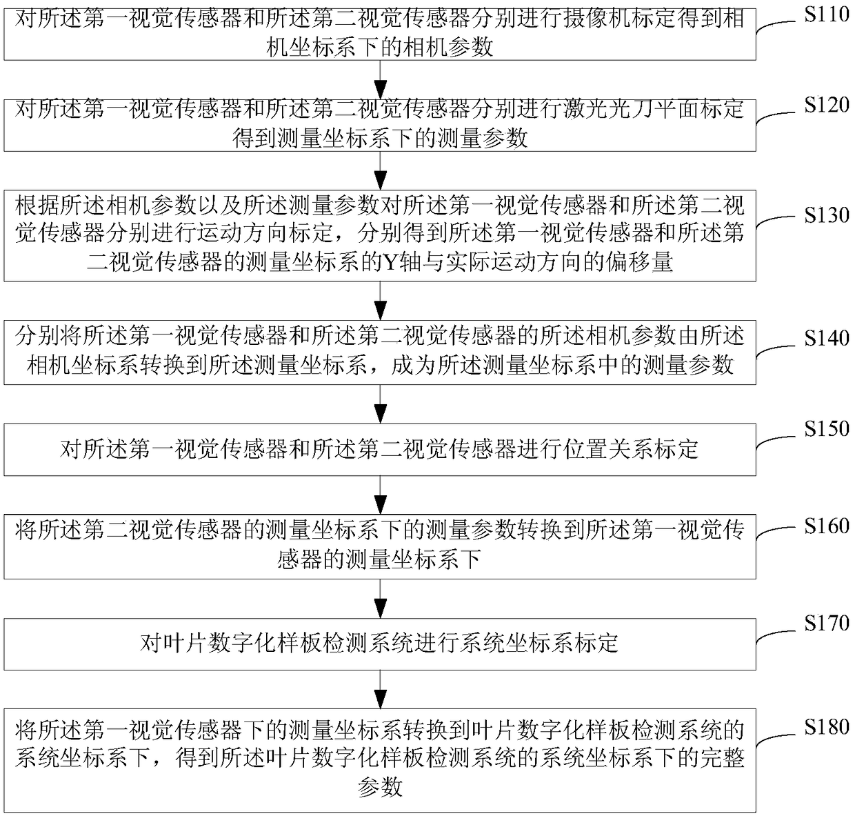
[0064] As the first aspect of the present invention, there is provided a calibration method for a blade digital template detection system, wherein the blade digital template detection system includes a first visual sensor and a second visual sensor, and the first visual sensor and the The second vision sensor is arranged symmetrically relative to each other, such as figure 1 As shown, the calibration method of the blade digital template detection system includes:

[0065] S110. Perform camera calibration on the first visual sensor and the second visual sensor respectively to obtain camera parameters in the camera coordinate system;

[0066] S120. Perform laser...


PUM


Abstract

The invention discloses a calibration method and device of a blade digitalized templet detection system, and relates to the technical field of visual measurement. The method comprises that camera calibration is carried out on first and second visual sensors; laser knife planar calibration is carried out on the two visual sensors; motion direction calibration is carried out on the two visual sensors according to camera and measurement parameters; the camera parameters of the two visual sensors are converted into a measurement coordinate system; the position relation of the two visual sensors iscalibrated; the measurement parameter in the measurement coordinate system of the second visual sensor is converted to the measurement coordinate system of the first visual sensor; the system coordinate system is calibrated; and the measurement coordinate system of the first visual sensor is converted to the system coordinate system. The calibration method is complete.

Description

technical field [0001] The invention relates to the technical field of visual measurement, in particular to a calibration method for a blade digital sample detection system and a calibration device for a blade digital sample detection system. Background technique [0002] Gas turbines are widely used in aviation, aerospace, energy and other fields. As the core parts of gas turbines, turbine blades have the characteristics of complex structure, high manufacturing process requirements, and many measurement parameters. Their shape errors affect the energy conversion efficiency of the entire gas turbine. Therefore, It puts forward requirements for the accuracy and effectiveness of irregular surface measurement. The calibration methods of different blade measurement methods directly determine the accuracy of the entire measurement, reflecting the applicability, economy, and efficiency of the measurement method. In order to be applicable to the blade measurement characteristics o...

Claims


Application Information

Patent Timeline
Patent Type & Authority Applications(China)
IPC IPC(8): G01B11/00
CPCG01B11/00G01B21/042
Inventor 张旭郑泽龙蔡永凯浦栋麟
Owner JIANGSU JITRI HUST INTELLIGENT EQUIP TECH CO LTD
Why Eureka
Try Eureka