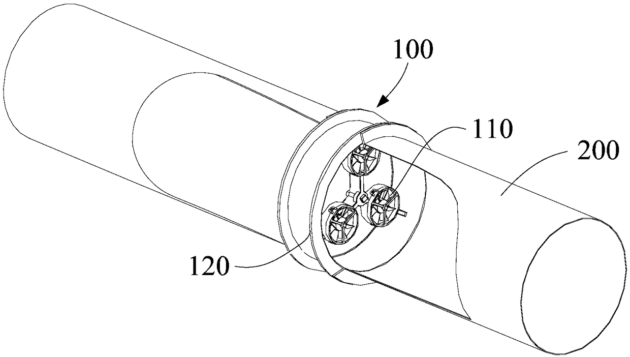
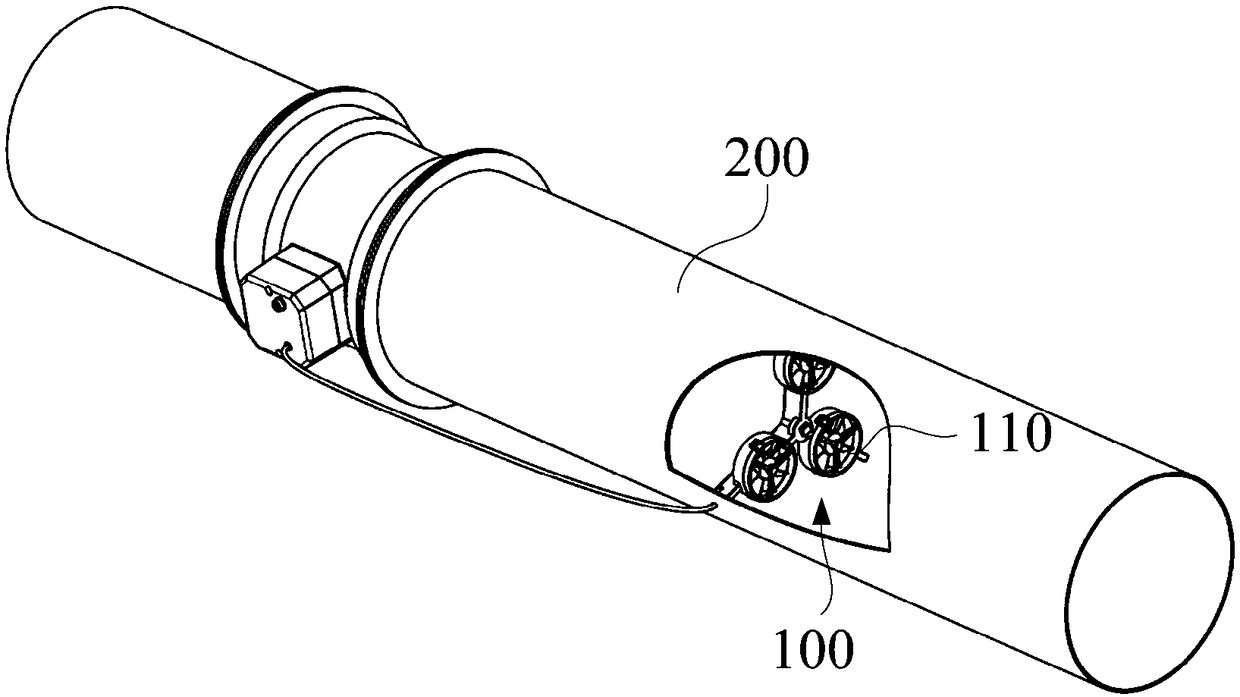
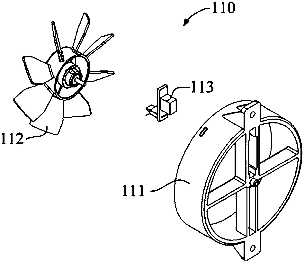
Wind speed measuring device, air valve and air volume adjusting system
A wind speed measurement and air valve technology, applied to valve devices, devices using electric/magnetic methods, and detecting the direction of fluid flow by measuring pressure difference, which can solve the problem of difficulty in obtaining the real wind speed of the air duct stably, anti-fluctuation, and anti-interference. Poor ability, inability to accurately adjust the air volume of the air duct, etc., to achieve the effect of strong anti-fluctuation, strong anti-interference, high measurement and control accuracy
- Summary
- Abstract
- Description
- Claims
- Application Information
AI Technical Summary
Problems solved by technology
Method used
Image
Examples
Embodiment 1
[0083] Please refer to Figure 7a , in this embodiment, the wind speed measuring device 100 communicates with the air duct 200, the wind speed measuring device 100 has a housing 120, the housing 120 has a cylindrical inner wall, and the cylindrical inner wall defines a circular ventilation section with a diameter of D=200mm S. Two impeller-type anemometers 110 are arranged in the casing 120, and the distances between the center of each impeller-type anemometer 110 and the central axis of the casing 120 are respectively: anemometer 1 is R 1 =52mm, anemometer 2 is R 2 = 59.5 mm.
[0084] The actual wind speed in the air duct is set to be 5m / s (when the wind speed measuring device 100 is tested, the actual wind speed in the air duct can be set by the wind generating device), and the wind speed values measured by each impeller anemometer 110 are in turn: 4.9669m / s, 5.0327m / s, taking the average value of the above wind speed values, the final measured wind speed value is 4.999...
Embodiment 2
[0086] Please refer to Figure 7b , in this embodiment, the wind speed measuring device 100 communicates with the air duct 200, the wind speed measuring device 100 housing 120, the housing 120 has a cylindrical inner wall, and the cylindrical inner wall defines a circular ventilation section S with a diameter D=250mm . Three impeller-type anemometers 110 are arranged in the casing 120, and the distances from the center of each impeller-type anemometer 110 to the central axis of the air duct 200 are respectively: anemometer 1 is R 1 =52mm, anemometer 2 is R 2 =63mm, anemometer 3 is R 3 =84.5mm.
[0087]The actual wind speed in the air duct is set to 5m / s, and the wind speed values measured by each impeller anemometer 110 are 4.86m / s, 4.97m / s, and 5.12m / s in turn, and the average value of the above wind speed values is taken to finally obtain The measured wind speed is 4.98m / s. That is, using the wind speed measurement device 100 provided in this embodiment, the differe...
Embodiment 3
[0089] Please refer to Figure 7c , in this embodiment, the wind speed measuring device 100 communicates with the air duct 200, the wind speed measuring device 100 housing 120, the housing 120 has a cylindrical inner wall, and the cylindrical inner wall defines a circular ventilation section S with a diameter D=500mm . Five impeller anemometers 110 are arranged in the casing 120, and the distances between the center of each impeller anemometer 110 and the central axis of the casing 120 are respectively: anemometer 1 is R 1 =52mm, anemometer 2 is R 2 =85mm, anemometer 3 is R 3 =130mm, anemometer 4 is R 4 =169mm, anemometer 5 is R 5 =208mm.
[0090] The actual wind speed in the air duct is set to be 5m / s, and the wind speed values measured by each impeller anemometer 110 are 4.67m / s, 4.91m / s, 5.05m / s, 5.15m / s, 5.19m / s, Taking the average value of the above wind speed values, the final measured wind speed value is 4.99m / s. That is, using the wind speed measuring device 1...
PUM
 Abstract
Description
Claims
Application Information
 - R&D
- Intellectual Property
- Life Sciences
- Materials
- Tech Scout
- Unparalleled Data Quality
- Higher Quality Content
- 60% Fewer Hallucinations
Browse by: Latest US Patents, China's latest patents, Technical Efficacy Thesaurus, Application Domain, Technology Topic, Popular Technical Reports.
© 2025 PatSnap. All rights reserved.Legal|Privacy policy|Modern Slavery Act Transparency Statement|Sitemap|About US| Contact US: help@patsnap.com


