Dual-motor automatic variable-speed transmission device of magnesium ore reaction kettle
An automatic variable speed and transmission technology, which is applied in the direction of transmission, gear transmission, transmission control, etc., can solve the problems of lack of variable speed transmission, difficulty in controlling time and finished product quality, and limitation of the scope of use of magnesium ore reactors. Sufficient suspension, excellent material mixing effect, and guaranteed material mixing effect
- Summary
- Abstract
- Description
- Claims
- Application Information
AI Technical Summary
Problems solved by technology
Method used
Image
Examples
Embodiment 1
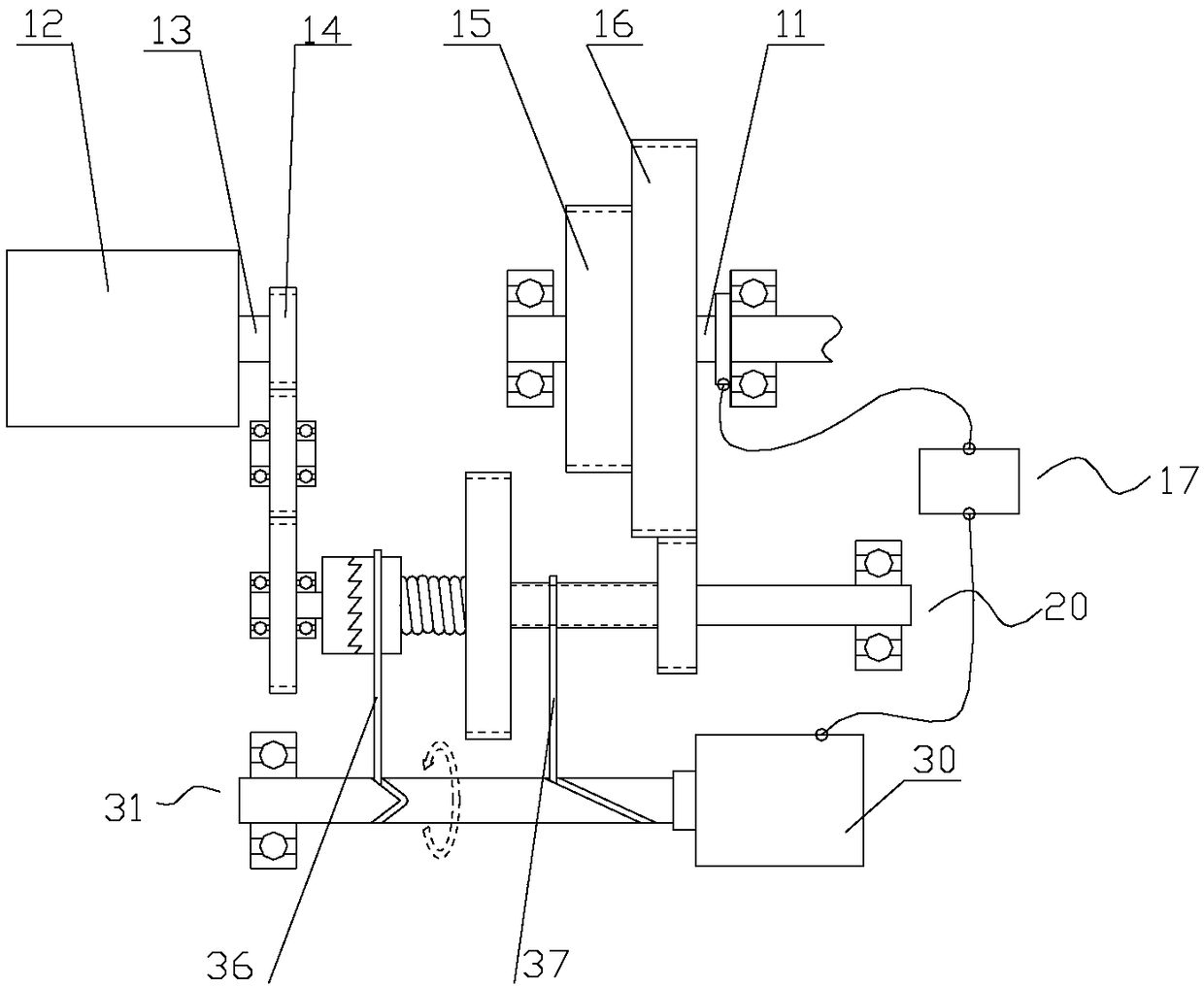
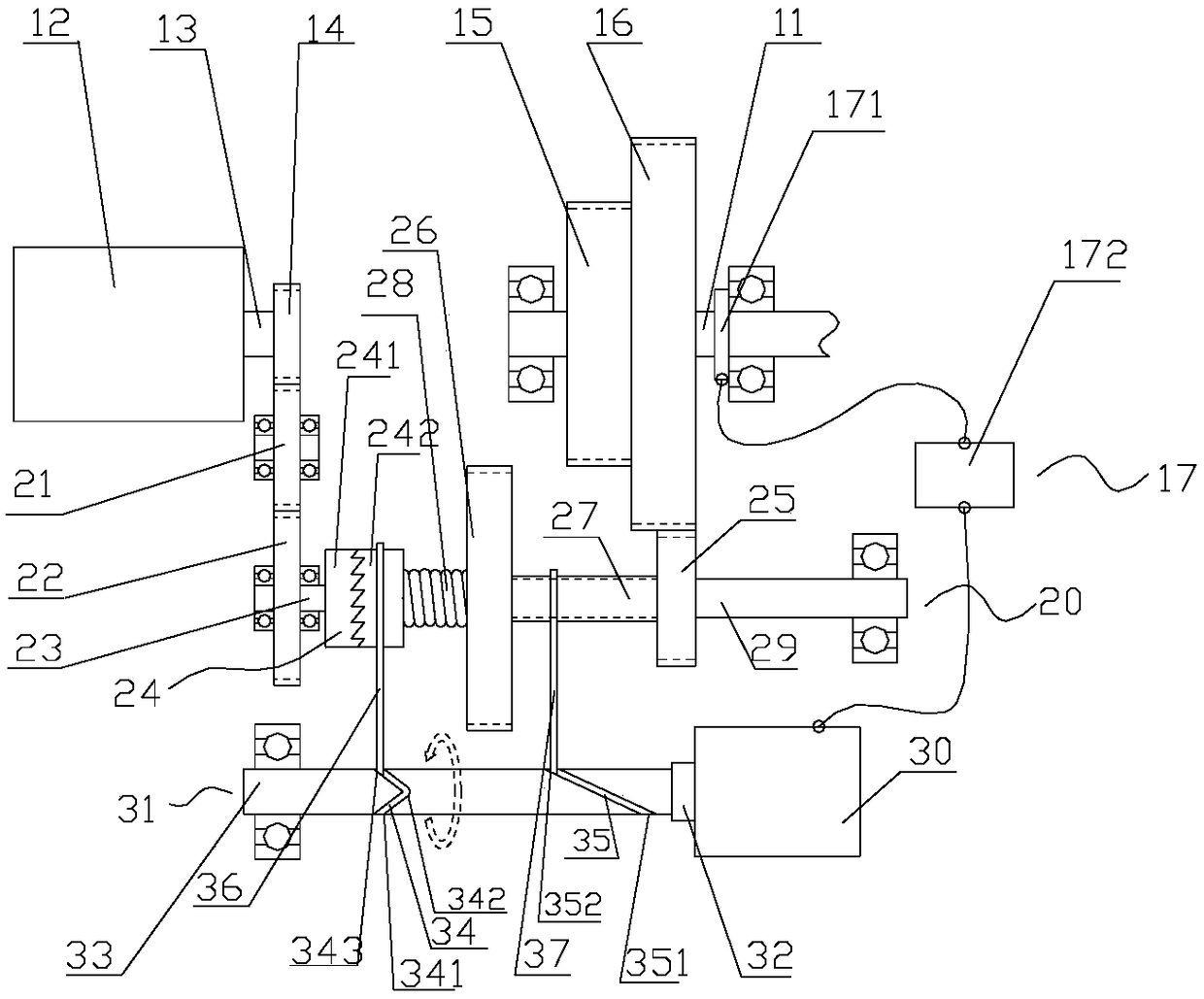
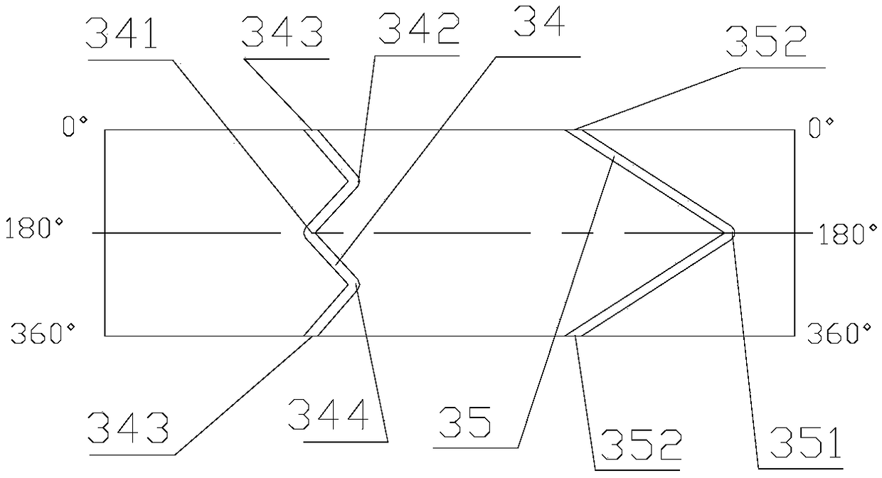
[0034] like figure 2 As shown, when the rotation speed of the stirring shaft 11 detected by the rotation speed sensor 171 is lower than the preset rotation speed value of the controller 172, the controller 172 of the rotation speed detection unit 17 does not issue a control command at this time, and the clutch lever 36 is positioned at The position of the inflection point III343 in the clutch chute 34 of the camshaft 33, the shift lever 37 is positioned at the position of the inflection point B352 in the shift chute 35, the clutch disc I241 and the clutch disc II242 of the clutch 24 are engaged with each other, and the speed change gear I25 It is in the state of meshing with the duplex gear II16 to form a transmission chain, which is low-speed output at this moment.
Embodiment 2
[0036] like Figure 5 As shown, when the speed sensor 171 detects that the rotation speed of the stirring shaft 11 is higher than the preset speed value of the controller 172, the controller 172 of the speed detection unit 17 sends a control command to the variable speed drive motor 30, and the variable speed drive motor 30 receives The control command triggers and drives the camshaft 33 to rotate. Due to the guidance of the clutch chute 34 and the speed change chute 35, the clutch lever 36 and the speed change lever 37 are respectively driven to move laterally to the right, and the camshaft 33 rotates from the original low-speed rotation state to At 90°, the clutch lever 36 moves along the clutch chute 34 and is located at the inflection point II 342, so that the moving shaft 27 moves relative to the clutch driven shaft 29, and the clutch disc I241 and clutch disc II 242 of the clutch 24 are separated; Move the speed change chute 35 to the middle position of inflection point ...
Embodiment 3
[0038] like Image 6 As shown, when the variable-speed drive motor 30 continues to drive the camshaft 33 to rotate to 180°, the clutch lever 36 moves along the clutch chute 34 and is located at the inflection point I341, and is pushed by the elastic tension of the elastic element 28 to make the movement The shaft 27 moves relative to the clutch driven shaft 29, and the clutch disc I241 and the clutch disc II 242 of the clutch 24 engage with each other again; and the shift lever 37 moves along the shift chute 35 to the inflection point A 351, so that the shift gear II 26 and the dual gear I15 is in the meshing state to form a transmission chain, which is high-speed output at this time.
PUM
 Abstract
Description
Claims
Application Information
 - R&D
- Intellectual Property
- Life Sciences
- Materials
- Tech Scout
- Unparalleled Data Quality
- Higher Quality Content
- 60% Fewer Hallucinations
Browse by: Latest US Patents, China's latest patents, Technical Efficacy Thesaurus, Application Domain, Technology Topic, Popular Technical Reports.
© 2025 PatSnap. All rights reserved.Legal|Privacy policy|Modern Slavery Act Transparency Statement|Sitemap|About US| Contact US: help@patsnap.com


