
Layer-by-layer optional dual mode cleaning device in metal 3D printing

A 3D printing and cleaning device technology, which is applied in the direction of dry gas arrangement, cleaning method and utensils, cleaning method using liquid, etc., can solve the problems of cleaning the device too hard, delaying the use time, single function, etc., to prevent dust from entering, good Shock-absorbing effect, effect of improving drug efficacy

Inactive Publication Date: 2018-11-23
ZHENGZHOU BINGTONG LIZHI ELECTRONICS TECH CO LTD +1
View PDF5 Cites 12 Cited by
  • Summary
  • Abstract
  • Description
  • Claims
  • Application Information

AI Technical Summary

Problems solved by technology

[0003] However, most of the existing cleaning devices used for metal 3D printing have simple structures and single functions, and the cleaning devices used are too hard, which will cause scratches on the cleaned items and affect normal use. It can be used only when it is dry, which delays the use time. Therefore, in order to make up for the above shortcomings, a layer-by-layer selective dual-mode cleaning device in metal 3D printing is proposed

Method used


Image

  • Layer-by-layer optional dual mode cleaning device in metal 3D printing
  • Layer-by-layer optional dual mode cleaning device in metal 3D printing
  • Layer-by-layer optional dual mode cleaning device in metal 3D printing

Examples


Embodiment Construction

[0027] The following will clearly and completely describe the technical solutions in the embodiments of the present invention with reference to the accompanying drawings in the embodiments of the present invention. Obviously, the described embodiments are only some, not all, embodiments of the present invention.

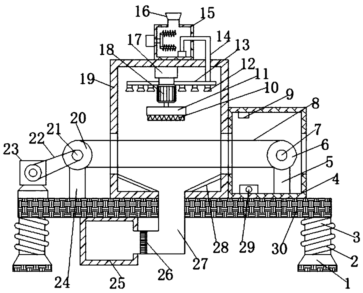
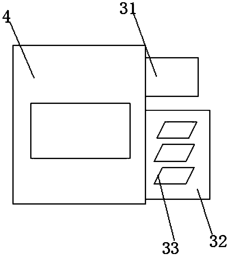
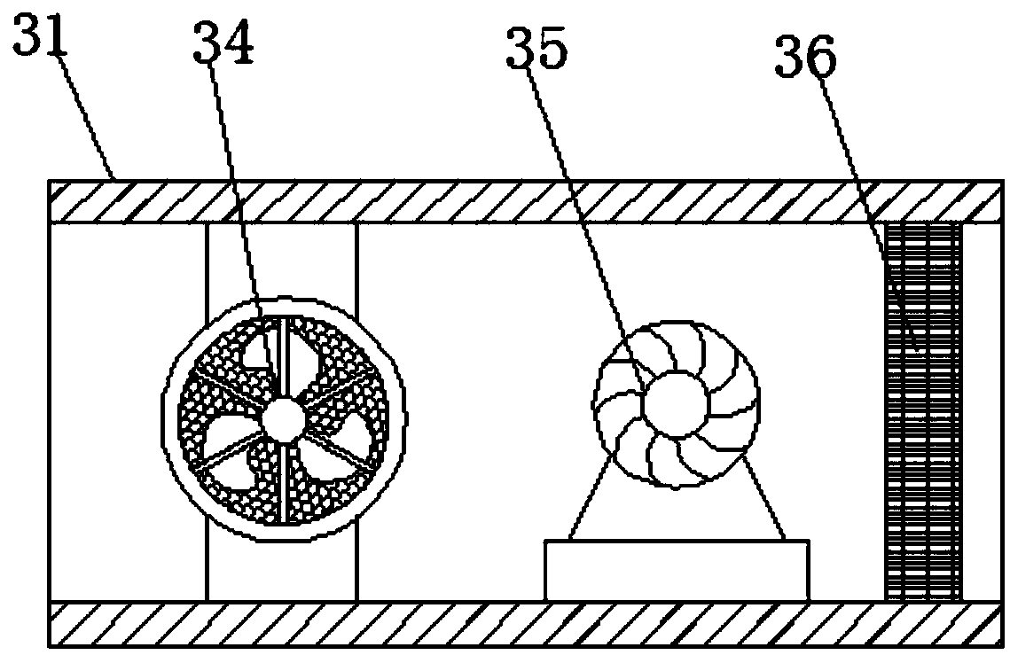
[0028] refer to Figure 1-5 , a layer-by-layer selective dual-mode cleaning device in metal 3D printing, comprising a bottom plate 30, a cleaning box 19 and a drying box 4, the top outer wall of the bottom plate 30 near the middle is fixed with a cleaning box 19 and a drying box. Dry box body 4, and the side outer wall that cleaning box body 19 and drying box body 4 are close to each other is all provided with rectangular hole communication hole, and the side outer wall that cleaning box body 19 and drying box body 4 are far away from each other is opened respectively. There is a feed port and a discharge port, and the top inner wall of the cleaning box body 19 is fi...


PUM


Abstract

The invention belongs to the technical field of cleaning equipment, and particularly relates to a layer-by-layer optional dual mode cleaning device in metal 3D printing. The layer-by-layer optional dual mode cleaning device in metal 3D printing solves the technical problem that the usage time is delayed caused by the fact that cleaned objects can only come into service after being naturally dried.According to the technical scheme, the layer-by-layer optional dual mode cleaning device in metal 3D printing comprises a base plate, a cleaning box body and a drying box body, wherein the cleaning box body and the drying box body are fixed to the top outer wall, close to the middle position, of the base plate through bolts, rectangular hole communicating holes are formed between the outer wallsof the sides, close to each other, of the cleaning box body and the drying box body, and a feed inlet and a discharge outlet are separately formed in the outer walls of the sides, far away from each other, of the cleaning box body and the drying box body. Through the arrangement of a heater and a warm air machine, the cleaned objects can be heated and dried so as to facilitate to come into servicefaster; and through the arrangement of a stirring motor, stirring rods and stirring blades, cleaning solution being added in a water tank can be adequately stirred with water to improve the pesticideeffect of the cleaning solution so as to facilitate to carry out cleaning work.

Description

technical field [0001] The invention relates to the technical field of cleaning devices, in particular to a layer-by-layer selective dual-mode cleaning device in metal 3D printing. Background technique [0002] With the development of science and technology, metal 3D printing technology is widely used in many fields such as jewelry, industrial design, architectural engineering and construction, education, etc. In metal 3D printing, layer by layer selective dual-mode will occur after long-term use. A certain amount of dust affects normal printing, which requires a cleaning device. [0003] However, most of the existing cleaning devices used for metal 3D printing have simple structures and single functions, and the cleaning devices used are too hard, which will cause scratches on the cleaned items and affect normal use. Therefore, in order to make up for the above shortcomings, a layer-by-layer selective dual-mode cleaning device in metal 3D printing is proposed. Contents o...

Claims


Application Information

Patent Timeline
Patent Type & Authority Applications(China)
IPC IPC(8): B08B1/04B08B1/02B08B3/02B08B13/00F26B21/00F26B15/04B08B1/20
CPCF26B15/04F26B21/00B08B3/022B08B13/00B08B1/20B08B1/32B08B1/12
Inventor 余东先何连连李加彦毛颖颖许晓辉
Owner ZHENGZHOU BINGTONG LIZHI ELECTRONICS TECH CO LTD
Learn More