Eureka AIR delivers breakthrough ideas for toughest innovation challenges, trusted by R&D personnel around the world.

Welding trolley and clamp switching system

A technology for switching systems and welding trolleys, applied in welding/cutting auxiliary equipment, welding equipment, auxiliary welding equipment, etc., can solve the problems of increased replacement costs, heavy trolley weight, inconvenient operation, etc., to reduce the number of uses, compatible Good performance and good stability

Pending Publication Date: 2018-11-23
LIUZHOU WULING MOTORS +1
View PDF0 Cites 5 Cited by
  • Summary
  • Abstract
  • Description
  • Claims
  • Application Information

AI Technical Summary

Problems solved by technology

[0004] In the prior art, the welding jig and the trolley are in an integrated structure. If the fixture is to be switched, the trolley needs to be connected to switch together. This structure requires a large number of trolleys, and the cost is high. At the same time, due to the weight of the trolley Larger, inconvenient operation and lower efficiency when switching
At present, there are often three ways to switch fixtures, manual switching, mechanical switching and automatic switching. Due to the heavy weight of the trolley, it needs to be replaced by a mobile trolley or a special spreader, which increases the replacement cost.

Method used


Image

  • Welding trolley and clamp switching system
  • Welding trolley and clamp switching system
  • Welding trolley and clamp switching system

Examples


Embodiment Construction

[0035] In order to enable those skilled in the art to better understand the technical solutions of the present invention, the present invention will be further described in detail below in conjunction with the accompanying drawings and specific embodiments.

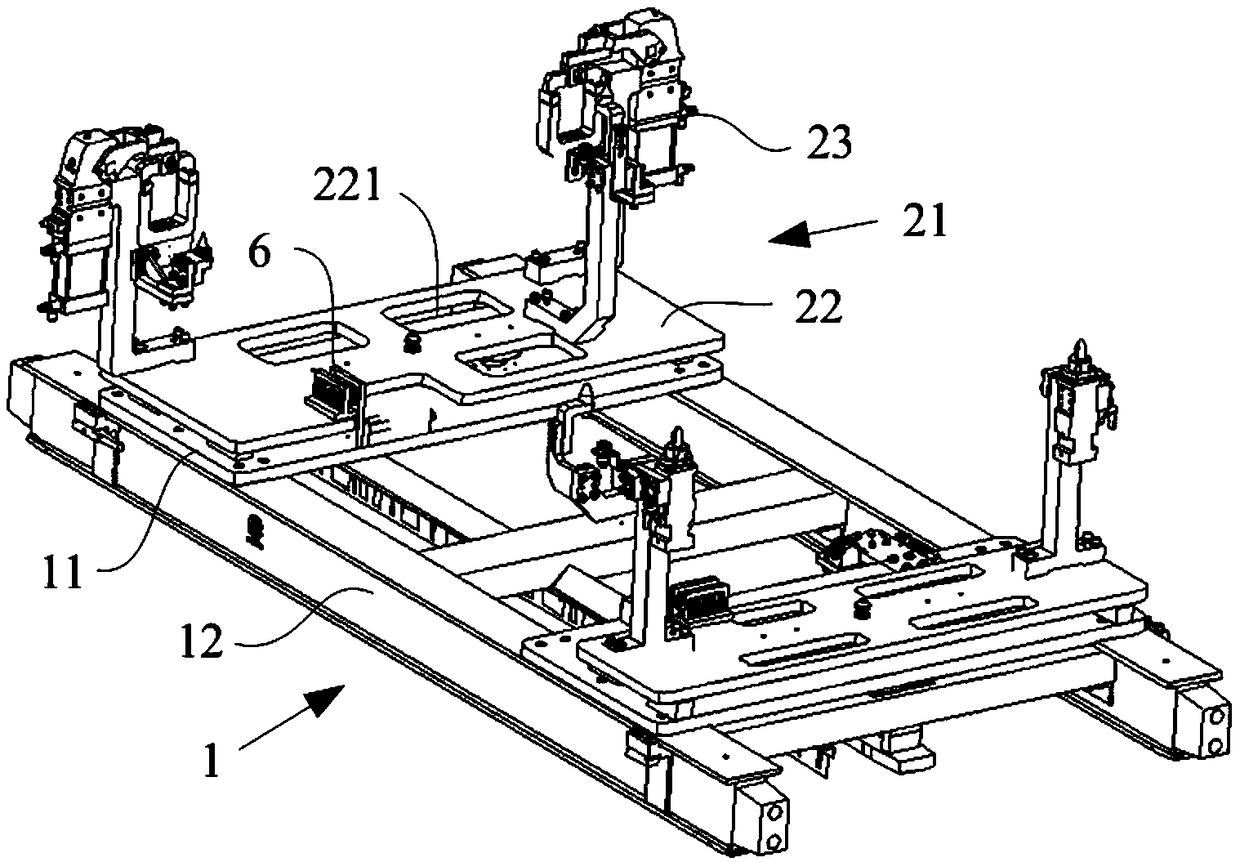
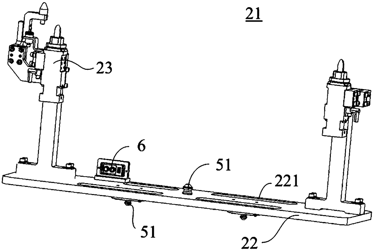
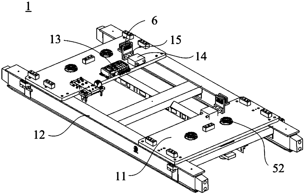
[0036] Please refer to Figure 1-5 , figure 1 It is a structural schematic diagram of the trolley installation fixture in the embodiment of the present invention; figure 2 yes figure 1 Schematic diagram of the structure of the middle fixture; image 3 yes figure 1 Schematic diagram of the structure of the trolley; Figure 4 is a schematic structural diagram of the robot and the storage library in the embodiment of the present invention; Figure 5 yes Figure 4 Schematic diagram of the structure of the rack.

[0037] An embodiment of the present invention provides a clamp switching system for a welding trolley, which includes a trolley 1, a fixture 2, a robot 3 and a storage library 4, wherein, as figure 1 and f...


PUM


Abstract

The invention relates to a welding trolley and clamp switching system. The welding trolley and clamp switching system comprises a trolley, a clamp, a robot and a storage warehouse, wherein the clamp comprises a bottom plate and a clamping unit which is fixedly arranged on the bottom plate; the clamping unit is used for positioning and clamping welding parts, and the bottom plate is separately anddetachably connected with the trolley and the robot through a zero point positioner; the storage warehouse is used for enabling the clamp to be placed; and the robot is used between the trolley and the storage warehouse and is used for transporting the clamp. According to the welding trolley and clamp switching system, the switching cost of the welding trolley and clamp switching system can be effectively reduced, a switching operation process is simplified and the switching efficiency is improved.

Description

technical field [0001] The invention relates to the technical field of welding equipment, in particular to a clamp switching system for a welding trolley. Background technique [0002] Due to the different digital and analog designs of the products, the welding positioning points and clamping positions are different during the production of the products. In order to ensure the quality of welding, the GD&T diagram is determined through process analysis, and the welding is carried out in different steps. In each step, different positioning points and clamping points need to be set, and the welding torch can be reached, and then the corresponding welding parameters can be matched to achieve the final result. Produce qualified products. [0003] Different positioning points and clamping position designs in the product production process lead to different clamping units of the corresponding welding fixtures. [0004] In the prior art, the welding jig and the trolley are in an i...

Claims


Application Information

Patent Timeline
Patent Type & Authority Applications(China)
IPC IPC(8): B23K37/04B23K37/00
CPCB23K37/00B23K37/0443
Inventor 丁刚强李坚刘杰谭达佩廖熙淘王钦
Owner LIUZHOU WULING MOTORS
Why Eureka
Eureka Blog
Learn More