Multifunctional instrument gauge transport case

An instrumentation and multi-functional technology, applied in the field of transport boxes, can solve the problems of poor structural strength and compressive performance, unfavorable fixed limit instrumentation, inability to monitor the existence of smoke, etc., to reduce workload, easy to carry and Transportation and fire prevention effect

Inactive Publication Date: 2018-11-23
WUHU WELLING DIGITAL TECH CO LTD
6 Cites 5 Cited by

AI-Extracted Technical Summary

Problems solved by technology

[0004] The purpose of the present invention is to provide a multi-functional instrument and instrument transport box, to solve the problem that the existing transport box proposed in the above background technology is not conducive to fixing the limit instrument,...

Method used

Principle of work: when in use, first open the cover body 4, the instrumentation that needs to be transported is placed in the inside of the inner box body 3, and by sliding the slider 22 on the electromagnetic slide rail 21 so as to control between the position-limiting splints 7 The distance between the instruments and meters should be limited and fixed. During the process of placing and transporting, the instruments and meters shake inside the device and cause collision damage. The shock-absorbing spring 2 plays the role of buffering and shock absorption to further protect the instruments and meters, and then cover the cover 4. The mechanical sealing ring 12 arranged between the cover body 4 and the outer box body 1 can ensure the airtightness of the device, avoid water body or dust intrusion, and cause pollution to instruments and meters. It can be converted into electrical energy and stored in the storage battery 23 to supply power to the device, which contributes to energy saving, emission reduction and environmental protection. During transportation, the telescopic rod 17 can be pulled out from the sleeve 20, and then transported by th...

Abstract

The invention discloses a multifunctional instrument gauge transport case. The case includes an outer case body, a solar panel, limiting clamp boards and a sleeve. A control panel is arranged at the center of one side of the outer case body, a storage battery is arranged at one end of the interior of the control panel, a single chip microcomputer is disposed at the other end of the interior of thecontrol panel, and buzzer alarms are arranged at the portions, on both sides of the control panel, of the outer case body; pulleys are uniformly arranged at one end of the other side of the outer case body, an anticorrosion layer is arranged on the outer side of the outer case body, an output end of a smoke sensor is electrically connected with an input end of the single chip microcomputer through a wire, and an output end of the single chip microcomputer is electrically connected with input ends of the buzzer alarms through wires. Through arrangement of the inner case body, an electromagnetic sliding rail, sliding blocks and the limiting clamp boards, the distance between the limiting clamp boards is conveniently adjusted by sliding the sliding blocks, and therefore instrument gauges different in size and specification are fixed.

Application Domain

Technology Topic

Image

  • Multifunctional instrument gauge transport case
  • Multifunctional instrument gauge transport case
  • Multifunctional instrument gauge transport case

Examples

  • Experimental program(1)

Example Embodiment

[0023] The technical solutions in the embodiments of the present invention will be clearly and completely described below in conjunction with the accompanying drawings in the embodiments of the present invention. Obviously, the described embodiments are only a part of the embodiments of the present invention, rather than all the embodiments. Based on the embodiments of the present invention, all other embodiments obtained by those of ordinary skill in the art without creative work shall fall within the protection scope of the present invention.
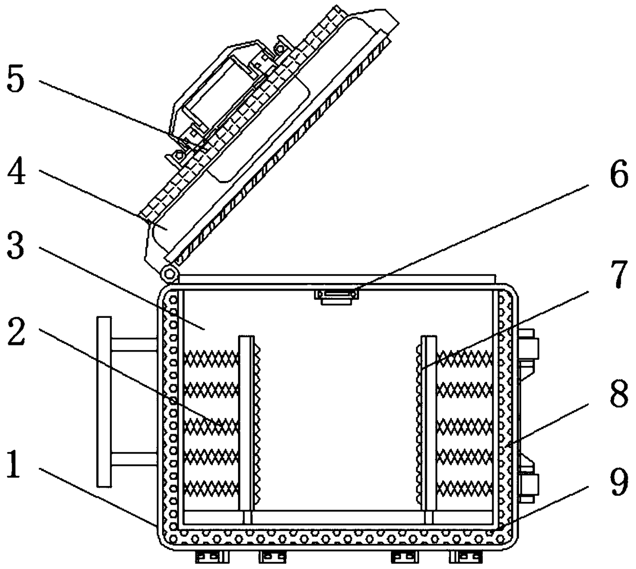
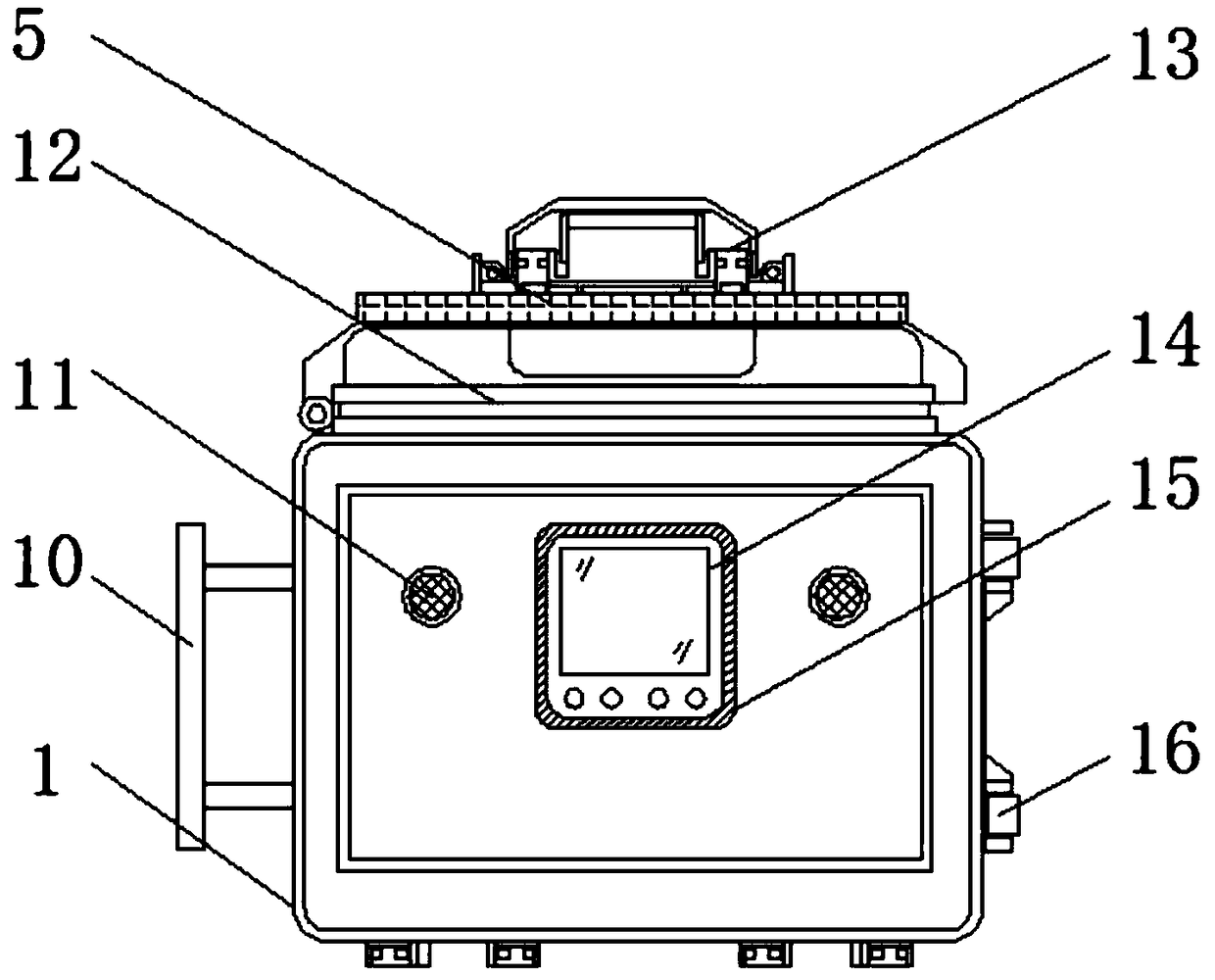
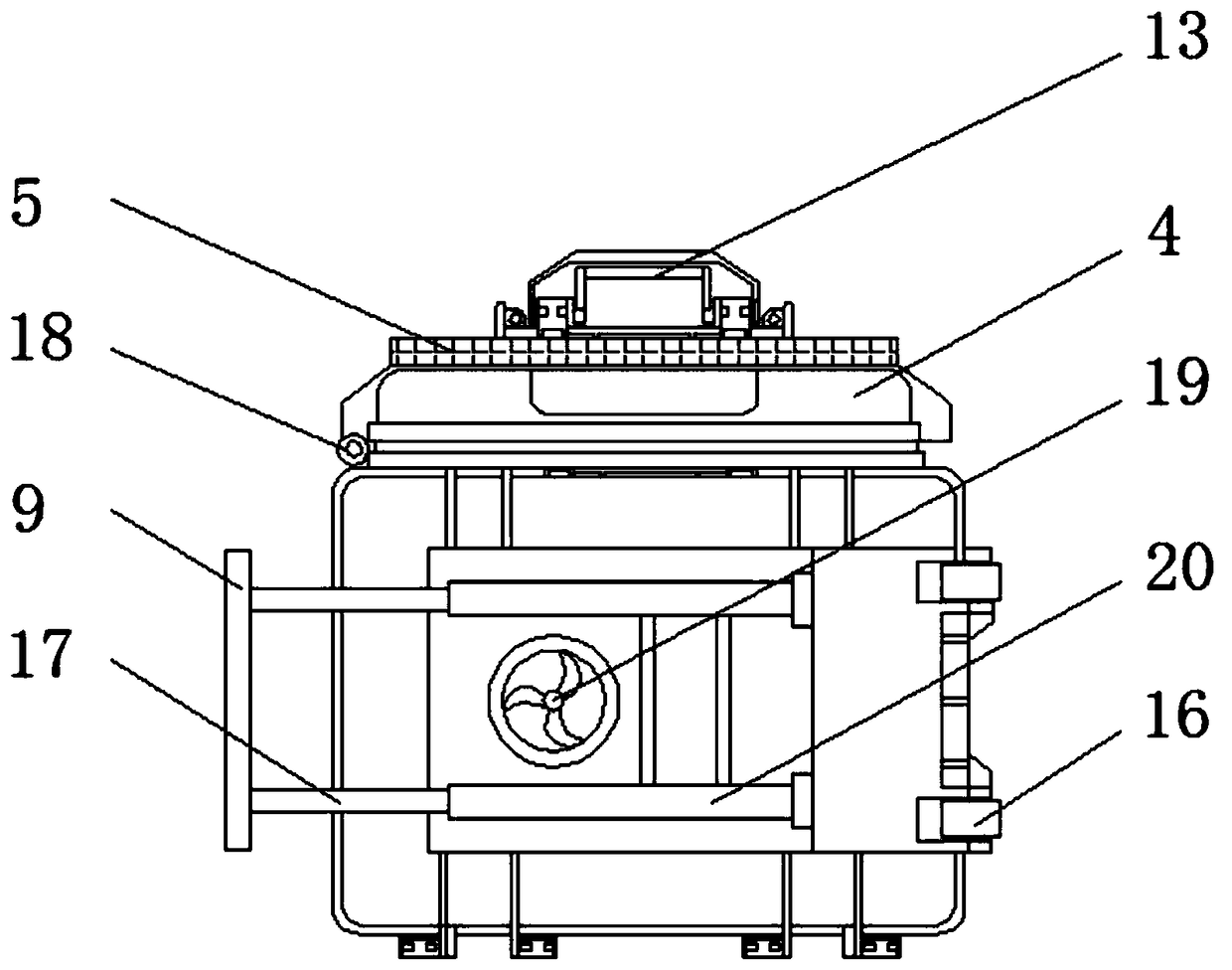
[0024] See Figure 1-6 , An embodiment provided by the present invention: a multifunctional instrument and meter transport box, including an outer box body 1, a solar panel 5, a limiting splint 7 and a sleeve 20, and a central position on one side of the outer box body 1 There is a control panel 14. The connection between the control panel 14 and the outer box 1 is provided with a rubber gasket 15 and the inner side wall of the control panel 14 is provided with a metal mesh layer 25 to avoid water infiltration and prevent external electromagnetic interference. The control panel 14 One end of the interior is provided with a battery 23, and the other end of the control panel 14 is provided with a single-chip microcomputer 24. The model of the single-chip 24 can be ZYWYKJ, and a buzzer 11 is provided on the outer box 1 on both sides of the control panel 14. The model of the alarm 11 can be QZBJ-260. A pulley 16 is evenly arranged at one end of the other side of the outer box 1, and a sleeve 20 is evenly arranged at the center of the other side of the outer box 1, between the sleeves 20 The outer box 1 is provided with a heat dissipation fan 19, and the air outlet of the heat dissipation fan 19 is provided with a filter screen to facilitate the ventilation and heat dissipation of the device. The sleeve 20 is provided with a telescopic rod 17 and the telescopic rod 17 is away from the pulley 16 A handle 10 is provided at one end of the telescopic rod 17 and the sleeve 20 constitutes a drawing structure, which is convenient to adjust the length of the telescopic rod 17, and the inner box body 3 is provided inside the outer box body 1, and the inner box body 3 and the outer box body A cavity 8 is formed between 1 and the interior of the cavity 8 is evenly filled with desiccant particles 9. Both ends of the inner bottom of the inner box 3 are equipped with limit clamps 7, and the bottom of the inner box 3 is equipped with electromagnetic slide rails 21. The bottom end of the limit clamp 7 is provided with a slider 22, and the sliders 22 are connected with the electromagnetic slide rail 21. The limit clamp 7 forms a sliding structure through the slider 22 and the electromagnetic slide 21 to facilitate the passage of the sliding slider 22 Adjust the distance between the limit splints 7 to fix and limit instruments of different sizes and specifications. The connection between the limit splint 7 and the inner wall of the inner box 3 is evenly provided with a shock-absorbing spring 2 to achieve The function of damping and buffering further protects the instruments and meters. The limit splint 7 is symmetrically distributed about the smoke sensor 6, and one side of the limit splint 7 is provided with sponge protrusions to avoid abrasion of the instruments and meters, and the inner box 3 A smoke sensor 6 is provided at the top. The model of the smoke sensor 6 can be MQ-2. The top end of the outer box 1 is hinged with a cover 4 through a hinge shaft 18, and the cover 4 forms a turning mechanism with the outer box 1 through a hinge shaft 18 , And the turning angle is 0-180°, which is convenient for placing instruments and meters, and a mechanical sealing ring 12 is arranged between the cover 4 and the outer box 1, and the top of the cover 4 is provided with a solar panel 5, and the solar panel 5 The output end of the solar panel is electrically connected to the input end of the battery 23 through the photovoltaic controller. A handle 13 is fixed on the top of the solar panel 5, a reinforcement layer 28 is provided inside the side wall of the outer box 1, and the reinforcement layer 28 is provided with The reinforcing ribs 29 are arranged at equal intervals in an "I"-shaped structure, which greatly improves the structural strength of the device and is not easy to be damaged. Moreover, both sides of the reinforcing layer 28 are provided with a compressive layer 27. The longitudinal section is semi-circular arc The anti-corrosion layer 26 is provided on the outer side of the outer box 1, and the output end of the smoke sensor 6 is electrically connected to the input end of the single chip computer 24 through a wire, and the output end of the single chip computer 24 is connected to the bee The input terminal of the buzzer 11 is electrically connected.
[0025] Working principle: When using, first open the cover 4, place the instruments and meters to be transported inside the inner box 3, and control the distance between the limit clamps 7 by sliding the slider 22 on the electromagnetic slide rail 21, The instruments and meters are limited and fixed, and the instruments and meters shake inside the device during transportation and cause collision damage. The shock-absorbing spring 2 acts as a buffer to further protect the instruments and meters, and then cover the cover 4 and the cover 4 The mechanical sealing ring 12 set between the outer box 1 and the outer box 1 can ensure the airtightness of the device, avoid water or dust intrusion, and cause pollution to the instruments and meters. The solar panel 5 on the cover 4 is convenient for converting light energy into The electric energy is stored in the battery 23 to supply power to the device, which helps to save energy, reduce emissions and protect the environment. The telescopic rod 17 can be drawn out of the sleeve 20 during transportation, and then transported by the handle 10 and the pulley 16 sliding device, which is convenient for reducing the staff The smoke sensor 6 inside the inner box 3 is convenient for monitoring whether there is smoke inside the device, and transmits the signal to the single-chip 24 when smoke occurs, and controls the buzzer 11 to alarm, reminding the staff to avoid occurrence Fire causes losses. The desiccant particles 9 arranged in the cavity 8 cooperate with the heat dissipation fan 19 to facilitate ventilation and heat dissipation of the device, to ensure internal drying, to avoid moisture in the instruments and meters, and to facilitate the use of the device. A reinforcement layer 28 and a compression layer 27 are arranged inside to improve the structural strength and compression performance of the device, so that it is not easily damaged by external extrusion. At the same time, an anti-corrosion layer 26 is provided on the outside of the outer box 1 to avoid the device from rusting. ,Extended service life.
[0026] For those skilled in the art, it is obvious that the present invention is not limited to the details of the foregoing exemplary embodiments, and the present invention can be implemented in other specific forms without departing from the spirit or basic characteristics of the present invention. Therefore, from any point of view, the embodiments should be regarded as exemplary and non-limiting. The scope of the present invention is defined by the appended claims rather than the foregoing description, and therefore it is intended to fall within the claims. All changes within the meaning and scope of equivalent elements of are included in the present invention. Any reference signs in the claims should not be regarded as limiting the claims involved.

PUM

no PUM

Description & Claims & Application Information

We can also present the details of the Description, Claims and Application information to help users get a comprehensive understanding of the technical details of the patent, such as background art, summary of invention, brief description of drawings, description of embodiments, and other original content. On the other hand, users can also determine the specific scope of protection of the technology through the list of claims; as well as understand the changes in the life cycle of the technology with the presentation of the patent timeline. Login to view more.

Similar technology patents

Continuous pyrolyzing furnace

InactiveCN106221714AGuaranteed tightnessConstant temperatureCharging-discharging device combinationsSpecial form destructive distillationPyrolysisContinuous feeding
Owner:HUNAN VARY TECH

Engine air filter discharge pipe sealing structure

InactiveCN1932278AGuaranteed tightnessSimple structure and implementationCombustion-air/fuel-air treatmentMachines/enginesEngineeringMuffler
Owner:CHONGQING CHANGAN AUTOMOBILE CO LTD

Buckle-type miniature rechargeable lithium battery structure member

InactiveCN109585721AIncrease squeezeGuaranteed tightnessFinal product manufactureCylindrical casing cells/batteryEngineeringRubber ring
Owner:WEIFANG YUYUAN ELECTRONICS CO LTD

Classification and recommendation of technical efficacy words

  • Guaranteed tightness
  • Protect environment

Method for recovering rare earth from waste rare earth luminescent material

InactiveCN102660688AHigh recovery rateProtect environmentGlass recyclingCerium oxides/hydroxidesRare-earth elementGlass matrix
Owner:UNIV OF SCI & TECH BEIJING

Environmental protective covering for electrical power connectors

InactiveUS7771221B1Efficient cable routingProtect environmentCouplings bases/casesEngineeringAll terrain vehicles
Owner:BLACKWELL DONALD A
Why Eureka
Try Eureka