Eureka AIR delivers breakthrough ideas for toughest innovation challenges, trusted by R&D personnel around the world.

Conveyor belt and carrier mounting structure, and feeding buffer device comprising same

A technology of installation structure and conveyor belt, which is applied in the direction of conveyors, conveyor objects, transportation and packaging, etc., can solve the problems of inability to meet product testing requirements, unstable product quality, poor transmission stability, etc., achieve good driving effect and save equipment Cost, the effect of increasing the intensity of use

Pending Publication Date: 2018-11-23
DONGGUAN GUANJIA ELECTRONICS EQUIP
View PDF7 Cites 7 Cited by
  • Summary
  • Abstract
  • Description
  • Claims
  • Application Information

AI Technical Summary

Problems solved by technology

Obviously, in this kind of production process, all aging and testing stations are manually operated, which takes up a lot of human resources, and there are potential safety hazards for personnel to suffer from work-related injuries. Moreover, products are placed and placed many times at aging and testing stations, which limits the expansion of production capacity. Improvement, not only low efficiency but also unstable product quality, unable to meet the needs of mass product testing
[0003] In the prior art, the Chinese patent application number is 201720506743.5, which discloses a high-precision positioning circular production line, including a power mechanism, a transmission mechanism, a conveying mechanism and a positioning mechanism, and the power mechanism, the transmission mechanism, the conveying mechanism and the positioning mechanism are all Installed on the bottom plate, the power mechanism includes a servo motor, a precision planetary reducer, the transmission mechanism includes a driving pulley, a driven pulley and a synchronous belt, the conveying mechanism includes a sliding seat trolley and a car track, and the positioning mechanism includes a thin-walled cylinder and a high-precision positioning column. ;The high-precision positioning ring production line is designed with independent working positioning components, which endows it with extremely flexible layout capabilities and ensures that other stations will not be affected in the event of a positioning group failure; the application of belt buckles is two Sufficient space is reserved for sub-fine positioning. The guide sleeve on the sliding seat trolley is designed with a guide angle, which can ensure the smooth secondary positioning and correction of the position of the trolley without affecting the working surface of the upper surface; The disadvantage is that it cannot be positioned in actual work, and the accuracy is not enough when the product needs to be put in or taken out, and the transmission stability is poor, resulting in low work efficiency and poor reliability.

Method used


Image

  • Conveyor belt and carrier mounting structure, and feeding buffer device comprising same
  • Conveyor belt and carrier mounting structure, and feeding buffer device comprising same
  • Conveyor belt and carrier mounting structure, and feeding buffer device comprising same

Examples


Embodiment Construction

[0026] The present invention will be further described below in conjunction with the accompanying drawings.

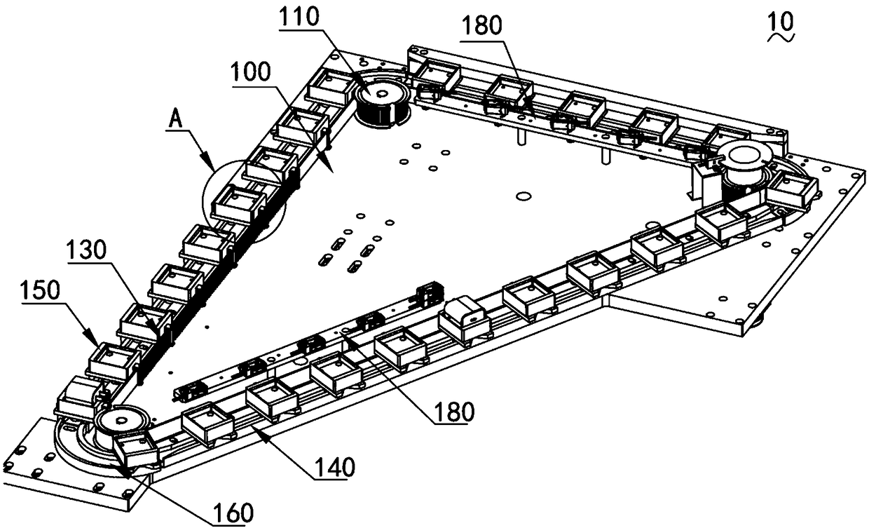
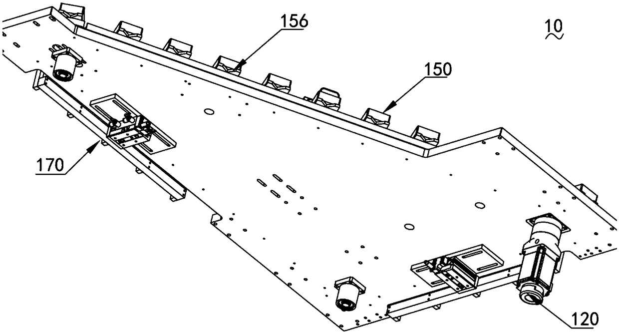
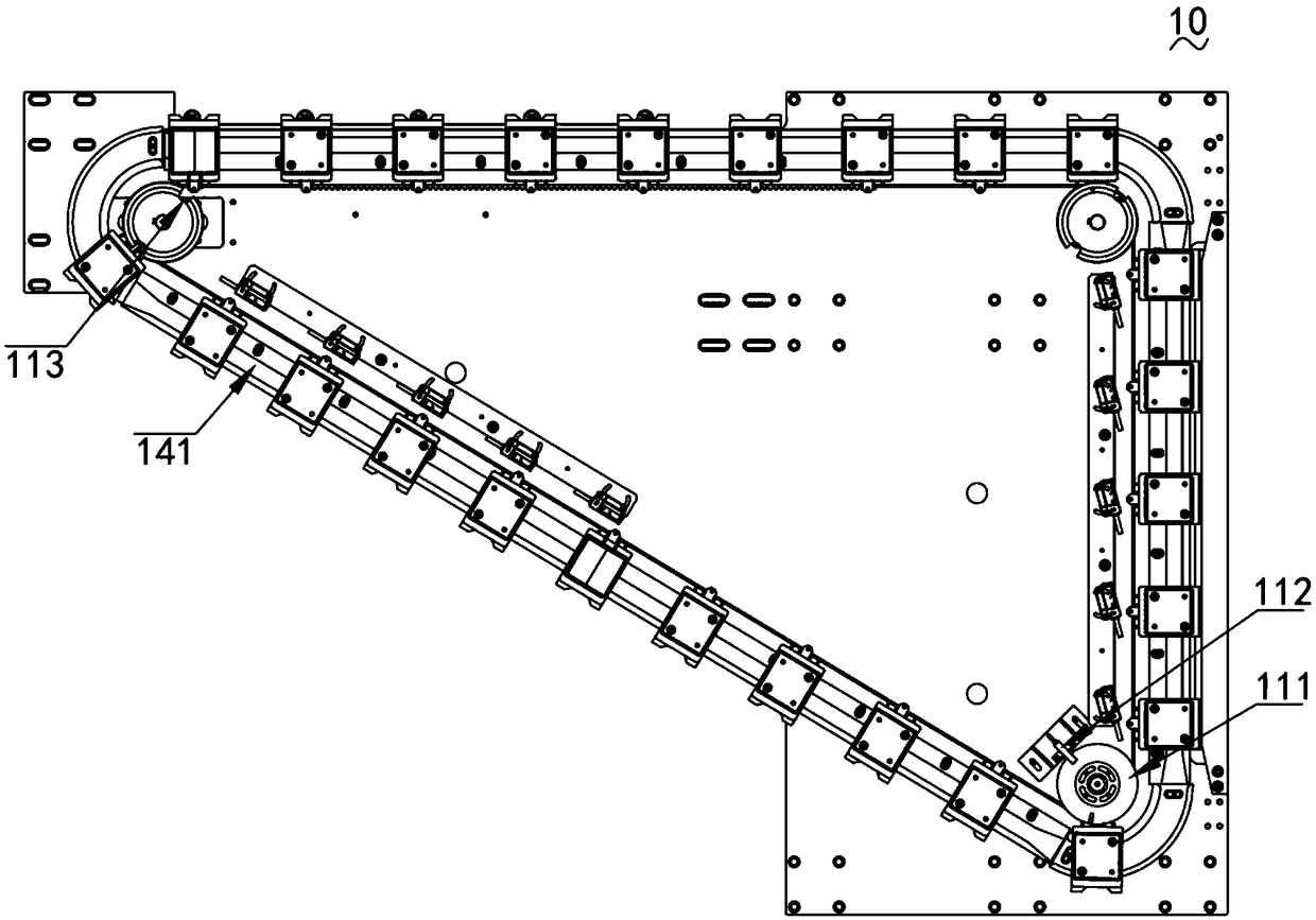
[0027] Such as Figure 1 ~ Figure 3 As shown, they are three-dimensional schematic diagrams of different viewing angles of the present invention.

[0028] The loading and buffering device 10 includes a workbench 100, a number of synchronous guide wheels 110 arranged on the workbench 100, at least two sets of synchronous guide wheels 110 are driven and connected to a drive assembly 120, and the conveyor belt 130 is connected to the synchronous guide wheels 110 by synchronous transmission. The workbench 100 is provided with a transmission guide rail 140 near the side of the conveyor belt 130, the carrier 150 is connected to the conveyor belt 130 and driven on the transmission guide rail 140, and the transmission guide rail 140 is provided with a curved groove 160 near the synchronous guide wheel 110, so The workbench 100 is provided with a positioning component 170 for ...


PUM


Abstract

The invention relates to the technical field of automatic feeding, in particular to a conveyor belt and carrier mounting structure, and a feeding buffer device comprising the same. The feeding bufferdevice comprises a workbench and a plurality of synchronous guiding wheels arranged on the workbench; the two or more sets of synchronous guiding wheels are in driving connection with driving assemblies; a conveyor belt is connected with the synchronous guiding wheels in a synchronous transmission mode; the side, close to the conveyor belt, of the workbench is provided with a transmission guidingrail; carriers are connected with the conveyor belt to be in transmission with the transmission guiding rail; the positions, close to the synchronous guiding wheels, of the transmission guiding rail are provided with bent grooves; and the workbench is provided with positioning assemblies for positioning the carriers. Direct connection of the conveyor belt and the carriers is adopted to achieve thetransmission effect, in the transmission process, the transmission stability is improved through the transmission guiding rail, the overall feeding buffer effect is good, the working efficiency is high, and reliability is high.

Description

technical field [0001] The invention relates to the technical field of automatic feeding, in particular to an installation structure of a conveyor belt and a carrier and a loading buffer device including the structure. Background technique [0002] With the development of society, people have higher and higher requirements for the quality of electronic products. In order to improve the quality of electronic products, it is necessary to carry out aging tests on electronic products before leaving the factory. In the prior art, when performing aging tests on electronic products, the test process is generally to manually transfer the products from the previous station through the belt when feeding. Put the product into the aging fixture to form aging electronic parts, then put the aging electronic parts into the aging place of the aging test rack for aging, after the aging is completed, manually take out the aging electronic parts for various performance tests, test When discha...

Claims


Application Information

Patent Timeline
Patent Type & Authority Applications(China)
IPC IPC(8): B65G17/12B65G15/30B65G17/36B65G15/36B65G21/22B65G47/88
CPCB65G15/30B65G15/36B65G17/12B65G17/36B65G21/22B65G47/88
Inventor 翟保利
Owner DONGGUAN GUANJIA ELECTRONICS EQUIP
Why Eureka
Eureka Blog
Learn More