
Tower crane blind area ultrathin steel plate shear wall hoisting device and hoisting method thereof

A steel plate shear wall and lifting device technology, which is applied in hoisting devices, hoisting devices, cranes, etc., can solve the problems that the boom tower crane cannot be installed in place, the installation cost is high, and the installation time is long, etc., so as to achieve flexible and convenient installation and disassembly , Low construction cost, and the effect of reducing the cost of measures

Inactive Publication Date: 2018-11-23
CCCC FIRST HARBOR ENG +1
View PDF9 Cites 2 Cited by
  • Summary
  • Abstract
  • Description
  • Claims
  • Application Information

AI Technical Summary

Problems solved by technology

[0003] At present, steel plate shear walls are directly hoisted by tower cranes or assisted by truck cranes for double-machine hoisting. After the hoisting is in place, the truck cranes are unhooked again. The installation cost is high, the installation time is long, and the efficiency is not high.
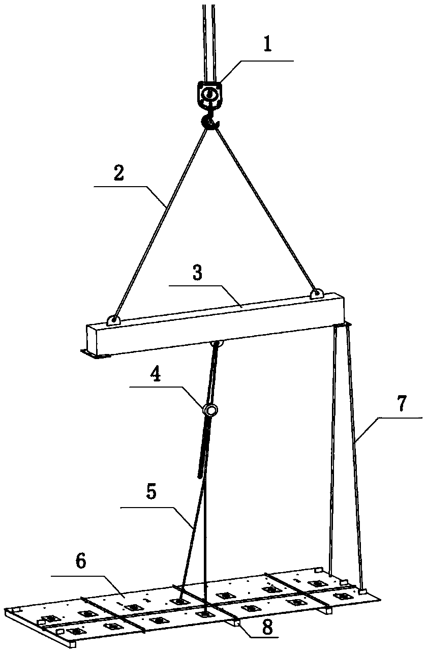
[0004] As for the steel plate shear wall within the blind area of ​​the tower crane, the boom tower crane cannot be installed in place, and a large truck crane is required for each hoisting. When the installation height of the steel plate shear wall increases, the installation cost is getting higher and higher. There is an urgent need for a The device with simple structure and convenient operation solves this problem

Method used


Image

  • Tower crane blind area ultrathin steel plate shear wall hoisting device and hoisting method thereof
  • Tower crane blind area ultrathin steel plate shear wall hoisting device and hoisting method thereof
  • Tower crane blind area ultrathin steel plate shear wall hoisting device and hoisting method thereof

Examples


Embodiment Construction

[0022] The present invention will be further described below in conjunction with embodiment:

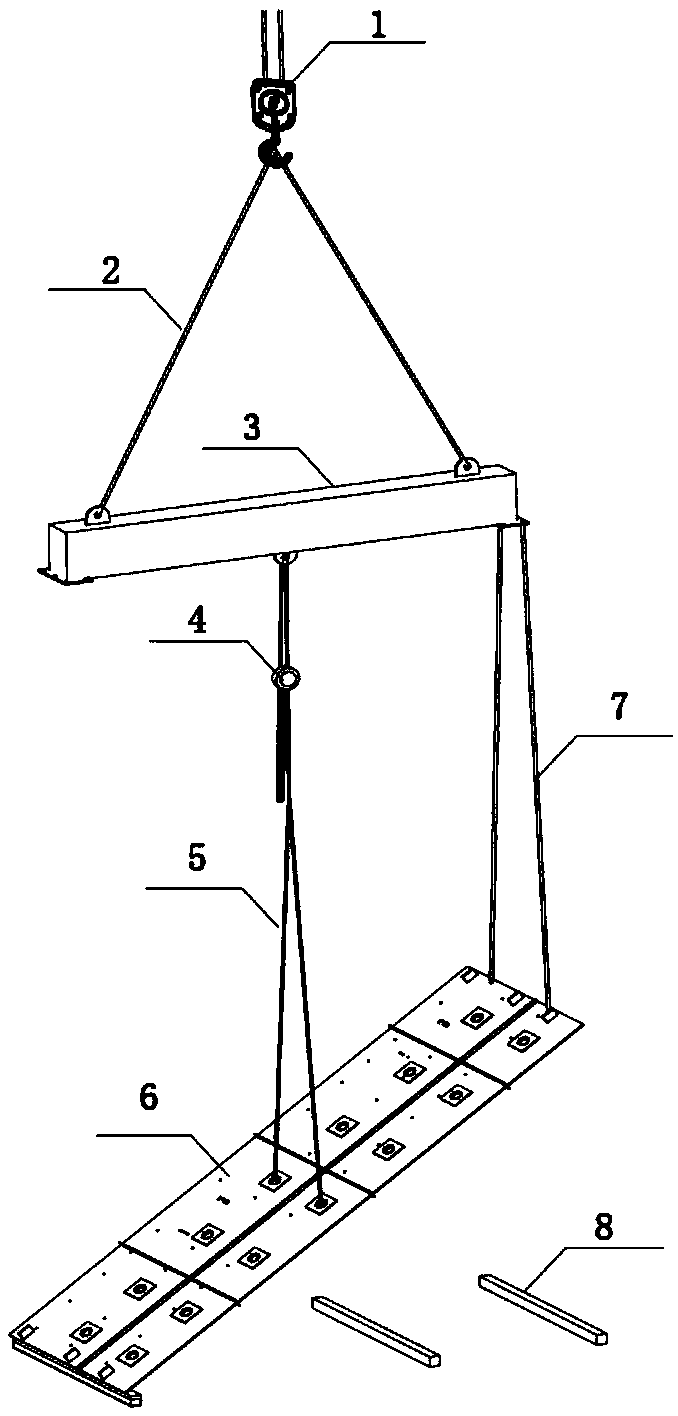
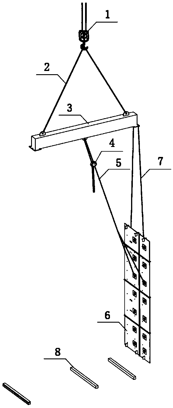
[0023] The lifting device of the present invention comprises a shoulder pole beam 3, and the pole pole beam 3 adopts a tower crane climbing steel beam, and two pole beam slings 7 for connecting with one end of the steel plate shear wall 6 are connected to one end of the lower surface of the pole pole beam 3, and An electric hoist 4 is arranged in the middle of the lower surface of the beam 3, and two electric hoist rigging 5 for connecting with the middle of the steel plate shear wall 6 are connected to the hooks of the electric hoist 4, and two electric hoist slings 5 ​​are connected to the upper surface of the shoulder beam 3 respectively. The hoisting sling 2 connected to the boom tower crane hook 1 also includes a plurality of sleepers 8 for padding up the steel plate shear wall 6 .

[0024] Lifting lugs are welded in the middle of the lower surface of the shoulder pole beam 3, a...


PUM


Abstract

The invention relates to the technical field of hoisting equipment, in particular to a tower crane blind area ultrathin steel plate shear wall hoisting device and a hoisting method thereof. The towercrane blind area ultrathin steel plate shear wall hoisting device comprises a shoulder pole beam, two shoulder pole beam riggings used for being connected with one end of a steel plate shear wall areconnected with one end of the lower surface of the shoulder pole beam, an electric hoist is arranged in the middle of the lower surface of the shoulder pole beam, a hook of the electric hoist is connected with two electric hoist riggings used for being connected with the middle of the steel plate shear wall, and the two ends of the upper surface of the shoulder pole beam are connected with two hoisting riggings connected with a lifting hook of a swing arm tower crane. The tower crane blind area ultrathin steel plate shear wall hoisting device and the hoisting method thereof are easy, convenient and rapid to operate, low in cost, safe and reliable and high in stability, and plastic deformation does not occur on the steel plate shear wall in the hoisting process.

Description

technical field [0001] The invention relates to the technical field of hoisting equipment, in particular to a hoisting device for an ultra-thin steel plate shear wall in a blind area of ​​a tower crane and a hoisting method thereof. Background technique [0002] Many buildings adopt steel plate shear wall structure, and the thickness of the steel plate may be gradually reduced from 60mm to 20mm. In particular, the maximum length of the 20mm steel plate shear wall section is 12m, and the width is only 3m, and it is located in the blind area of ​​the tower crane. It is difficult to turn over, lift and install the wall, and additional hoisting machinery is required to enter the site to cooperate. [0003] At present, steel plate shear walls are directly hoisted by tower cranes or assisted by truck cranes for double-machine hoisting. After hoisting is in place, the truck cranes are then unhooked. The installation cost is high, the installation time is long, and the efficiency is...

Claims


Application Information

Patent Timeline
IPC IPC(8): B66C1/12B66C23/62B66F19/00
CPCB66C1/12B66C23/62B66F19/00
Inventor 万瑞杨凯凯王根叶张保卫米向东
Owner CCCC FIRST HARBOR ENG
Learn More