
Sewage treatment device for cultivation greenhouse

A sewage treatment device and greenhouse technology, which is applied in water/sewage treatment, biological water/sewage treatment, light water/sewage treatment, etc., can solve the problems of large footprint, threat to life and health, and high construction cost, and achieve saving and cleaning cost, guarantee normal work, and improve work efficiency

Inactive Publication Date: 2018-11-23
QUZHOU KECHUANG IND DESIGN SERVICES
View PDF6 Cites 0 Cited by
  • Summary
  • Abstract
  • Description
  • Claims
  • Application Information

AI Technical Summary

Problems solved by technology

[0002] With the accelerated transformation of domestic farming methods from family free-range farming to large-scale farming, the pollution caused by farming is also increasing. Untreated farming sewage is directly discharged into the water body, which will not only make the water smelly, destroy the dynamic balance of the water body, and affect The surrounding environment will also cause groundwater to be polluted, which in turn poses a threat to people's life and health. In order to avoid this phenomenon, sewage treatment equipment is generally used to treat aquaculture sewage. Most of the existing sewage treatment equipment has complex structures, not only occupying an area The area is large, the construction cost is high, and it is inconvenient to maintain and manage. It is very unsuitable for small-scale farms. In addition, most sewage treatment devices use mains electricity to work, which has high operating costs and poor practicability.

Method used


Image

  • Sewage treatment device for cultivation greenhouse
  • Sewage treatment device for cultivation greenhouse
  • Sewage treatment device for cultivation greenhouse

Examples


Embodiment Construction

[0021] The following will clearly and completely describe the technical solutions in the embodiments of the present invention with reference to the accompanying drawings in the embodiments of the present invention. Obviously, the described embodiments are only some, not all, embodiments of the present invention. Based on the embodiments of the present invention, all other embodiments obtained by persons of ordinary skill in the art without making creative efforts belong to the protection scope of the present invention.

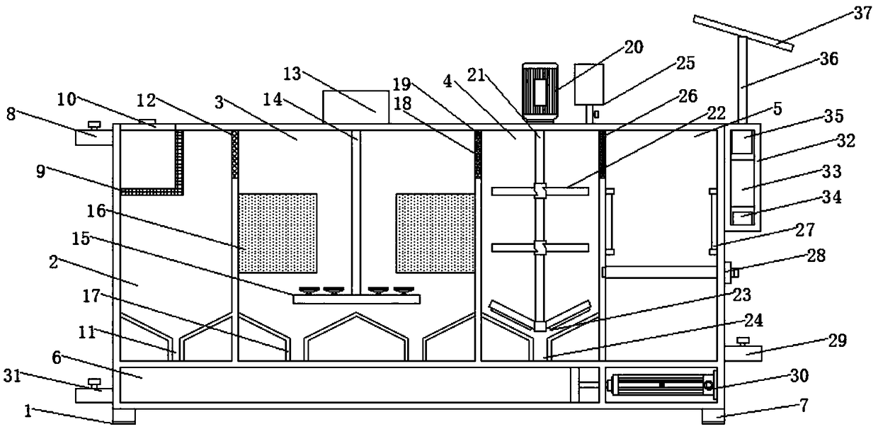
[0022] see Figure 1-5, the present invention provides a technical solution: a sewage treatment device for aquaculture greenhouses, including a device body 1, a primary sedimentation chamber 2, a biochemical chamber 3, a secondary sedimentation chamber 4, a disinfection chamber 5, a sludge chamber 6, and foot pads 7. Sewage inlet 8, grille 9, cleaning port 10, sewage outlet 11, water inlet tank 12, air pump 13, air intake pipe 14, air distribution pipe 15, bio...


PUM


Abstract

The invention discloses a sewage treatment device for a cultivation greenhouse. A primary sedimentation chamber is arranged at one side of a device body; a sewage inlet is arranged at the top end of the left side of the primary sedimentation chamber; a blow-off opening is formed in the bottom end in the primary sedimentation chamber; a sludge chamber is mounted at the bottom of the blow-off opening; a sludge cleaning device is mounted at the right side in the sludge chamber; an electric cylinder is arranged at one end of the sludge cleaning device; a push plate is mounted at one end of the electric cylinder; a sludge outlet is arranged at the left side of the sludge chamber; a biochemical chamber is mounted at the right side of the primary sedimentation chamber; a secondary sedimentation chamber is mounted at the right side of the biochemical chamber; a disinfection chamber is mounted at the right side of the secondary sedimentation chamber; a control box is mounted at the top end of the right side of the disinfection chamber; a clean water outlet is formed in the bottom end of the right side of the disinfection chamber. According to the sewage treatment device disclosed by the invention, the electric cylinder and the push plate are fixedly connected through a fastening part and are firm; the push plate can be used for cleaning sludge in the sludge chamber under the action of the electric cylinder and is flexible and rapid; normal work of the device body is ensured and the working efficiency of the device is improved; the burdens of workers are alleviated and the post-period cleaning cost is saved.

Description

technical field [0001] The invention relates to the technical field of a sewage treatment device, in particular to a sewage treatment device for aquaculture greenhouses. Background technique [0002] With the accelerated transformation of domestic farming methods from family free-range farming to large-scale farming, the pollution caused by farming is also increasing. Untreated farming sewage is directly discharged into the water body, which will not only make the water smelly, destroy the dynamic balance of the water body, and affect The surrounding environment will also cause the groundwater to be polluted, which in turn poses a threat to people's life and health. In order to avoid this phenomenon, sewage treatment equipment is generally used to treat aquaculture sewage. Most of the existing sewage treatment equipment has complex structures, not only occupying an area The area is large, the construction cost is high, and it is inconvenient to maintain and manage. It is not...

Claims


Application Information

Patent Timeline
Patent Type & Authority Applications(China)
IPC IPC(8): C02F9/14
CPCC02F1/001C02F1/32C02F1/52C02F1/5281C02F3/00C02F3/02C02F9/00C02F2001/007C02F2201/009C02F2303/04
Inventor 覃庆冬
Owner QUZHOU KECHUANG IND DESIGN SERVICES
Learn More