Wastewater sludge recovery treatment device

A technology for recycling and sludge treatment, applied in water/sludge/sewage treatment, sludge treatment, dehydration/drying/concentrated sludge treatment, etc., can solve problems affecting filtration efficiency, stability, and slow sludge recovery efficiency , to achieve the effect of improving precipitation efficiency, reducing temperature loss and improving mixing efficiency

Inactive Publication Date: 2018-11-23
陈多玉
View PDF0 Cites 17 Cited by
  • Summary
  • Abstract
  • Description
  • Claims
  • Application Information

AI Technical Summary

Problems solved by technology

[0003] However, the existing waste water sludge recovery treatment device has a simple structure. Generally, the waste water is filtered to recycle the sludge. The recovery efficiency of the sludge is slow and the recovery effect is poor. The water content in the recycled sludge is relatively large. During the transfer, sewa

Method used


Image

  • Wastewater sludge recovery treatment device
  • Wastewater sludge recovery treatment device
  • Wastewater sludge recovery treatment device

Examples


Embodiment 1

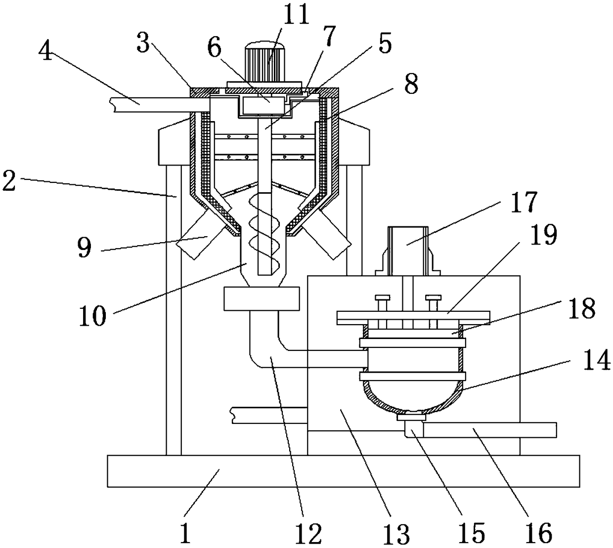
[0025] Embodiment one: refer to Figure 1-4 , a waste water sludge recovery treatment device, including a base 1 and a sludge recovery bin 3, the base 1 is fixed with a sludge recovery bin 3 through a pillar 2, and a sewage inlet pipe 4 is connected to the side wall of the sludge recovery bin 3, The first drive motor 11 is fixed to the center of the top of the sludge recovery bin 3 by bolts, and the bottom of the first drive motor 11 is connected to the stirring shaft 5 in rotation. The inside of the sludge recovery bin 3 is fixed with a filter cover 8, and the bottom of the sludge recovery bin 3 An outlet pipe 9 is connected to the outer wall, a first mud discharge pipe 10 is connected to the center of the bottom of the filter cover 8, a dewatering box 13 is fixed on the side of the sludge recovery bin 3 on the base 1, and a dewatering box 13 is fixed inside the dewatering box 13. Press filter tank 14, the top bolt of press filter tank 14 is fixed with sealing cover plate 19,...

Embodiment 2

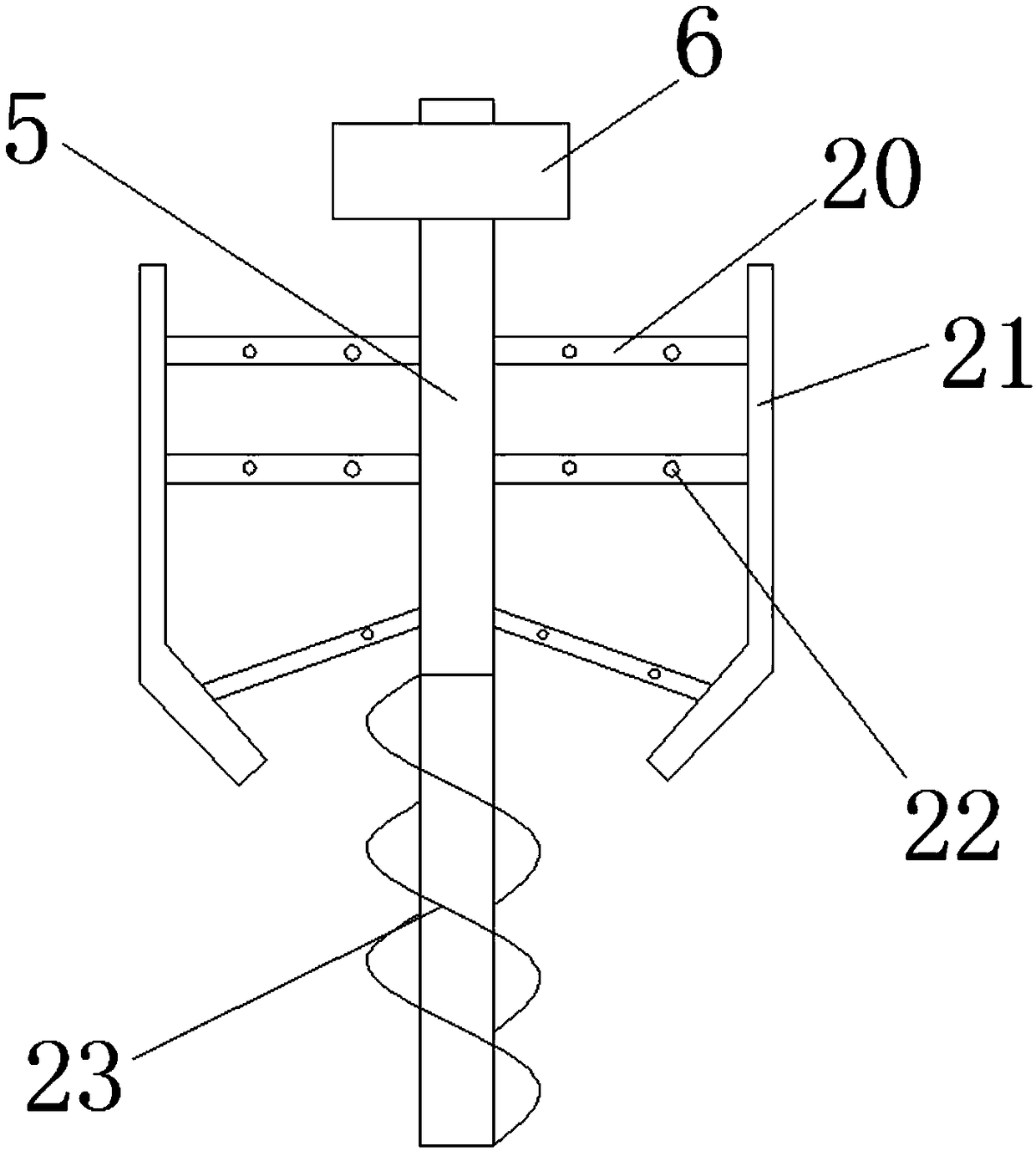
[0026] Embodiment two: refer to Figure 1-2 , the stirring shaft 5 is sleeved and fixed with a flocculant box 6, and the flocculant box 6 is conductively connected with the stirring shaft 5, and the flocculant box 6 is connected with a feeding pipe 7, and the stirring shaft 5 is welded with a scraper through the stirring rod 20 Plate 21, the stirring rod 20 is provided with a liquid outlet 22, the bottom end of the stirring shaft 5 is connected with a screw feeding rod 23, and the screw feeding rod 23 is located inside the first mud discharge pipe 10, the stirring shaft 5 and the stirring plate 20 are all internal hollow structures, and the stirring shaft 5 and the stirring rod 20 are connected to each other, the flocculant in the flocculant box 6 can be transferred to the stirring rod 20 through the stirring shaft 5, and the liquid outlet hole 22 opened on the stirring rod 20 The discharge is mixed with the sewage, and the auxiliary stirring by the stirring rod 20 effectively...

Embodiment 3

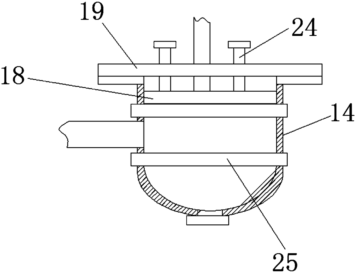
[0027] Embodiment three: refer to figure 1 and image 3 , the pressure plate 18 is welded with a limit shaft 24 that runs through the sealing cover plate 19, and the top end of the limit shaft 24 is welded with a limit block. There are three limit shafts 24, and the three limit shafts 24 are arranged in a ring shape. The spacing between the two adjacent limit shafts 24 is equal, and the outer wall of the pressure filter tank 14 is sleeved with a ring frame 25. The limit shaft 24 is used to limit the position of the pressure plate 18, which improves the stability and stability of the pressure plate 18 moving up and down. 18, the setting of ring frame 25 is used to improve the intensity of pressure filter tank 14.


PUM


Abstract

The invention discloses a wastewater sludge recovery treatment device. The device comprises a base and a sludge recovery bin, wherein the sludge recovery bin is fixed to the base through a supportingcolumn, a sewage inlet pipe is connected with one side wall of the sludge recovery bin, a first driving motor is fixed to the center part of the top of the sludge recovery bin through bolts, a stirring shaft is rotatably connected with the bottom of the first driving motor, a filtering cover is fixed to the interior of the sludge recovery bin, water outlet pipes are connected with the outer surface wall of the bottom of the sludge recovery bin, and a first sludge discharging pipe is connected with the center part of the bottom of the filtering cover. In the wastewater sludge recovery treatmentdevice, the sludge recovery bin, a dehydration box and a second sludge discharging pipe which is provided with electric heating pipes and used for drying are arranged, thus sludge in wastewater can be directly recovered, dehydrated and dried, the integration level is high, functions are complete, use is convenient, the sludge subjected to recovery treatment can be directly transferred, and duringtransferring, no sewage percolates, so that the environment is protected.

Description

technical field [0001] The invention relates to the technical field of waste water sludge treatment, in particular to a recovery treatment device for waste water sludge. Background technique [0002] Wastewater sludge refers to the accumulated solid sediment separated from various types of water, wet or mixed with liquid components, is the product of natural or artificial treatment processes, urban sewage, water supply plants and industrial wastewater treatment stations, in the production process A large amount of sludge is continuously discharged in the sewage plant, and the amount of sludge in the sewage plant accounts for about 0.3%~0.5%± (calculated with a water content of 97%) of the treatment capacity. These sludge need further treatment. [0003] However, the existing waste water sludge recovery treatment device has a simple structure. Generally, the waste water is filtered to recycle the sludge. The recovery efficiency of the sludge is slow and the recovery effect is...

Claims


Application Information

Patent Timeline
IPC IPC(8): C02F11/12C02F1/52
CPCC02F11/122C02F1/5281C02F11/12
Inventor 陈多玉
Owner 陈多玉
Why Eureka
Try Eureka