Vegetated ditch rainwater drainage pipe gallery system and construction method

A technology for planting grass ditches and drainage pipes, applied in water conservancy projects, artificial islands, underwater structures, etc., can solve problems such as water and soil loss, poor plant growth, deterioration and odor in grass planting ditches, and achieve the effect of ensuring healthy growth

Active Publication Date: 2018-11-23
上海佳长环保科技有限公司
View PDF5 Cites 4 Cited by
  • Summary
  • Abstract
  • Description
  • Claims
  • Application Information

AI Technical Summary

Problems solved by technology

In the existing urban construction, the use of rainwater is mainly when it rains, and the rainwater directly flows into the sewer pipe gallery through the road surface, and the pipe gallery stores the rainwater. purpose; the above will bring about a problem, the rainwater entering the sewer pipe gallery will cause deterioration and odor if it is not used for a long time; moreover, the existing technology cannot clean the grass ditch in the city (the machine non-separation zone of the road) Or the place where the central divider is planted with greenery is called the grass-planting ditch) for effective use of rainwater. When it rains, the rainwater is directly discharged into the road, which will not only cause the rainwater to not be used effectively, but also pollute the road surface with the mixture of rainwater and soil. It will also cause the grass-planting ditch Inner water and soil erosion, which in turn leads to unstable plant rooting and poor plant growth

Method used


Image

  • Vegetated ditch rainwater drainage pipe gallery system and construction method
  • Vegetated ditch rainwater drainage pipe gallery system and construction method
  • Vegetated ditch rainwater drainage pipe gallery system and construction method

Examples


Embodiment Construction

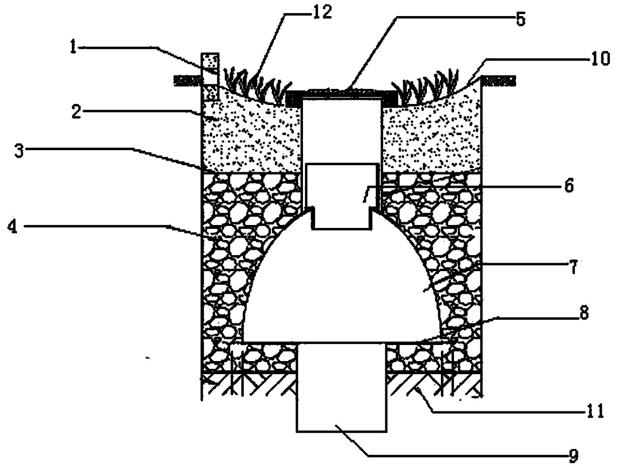
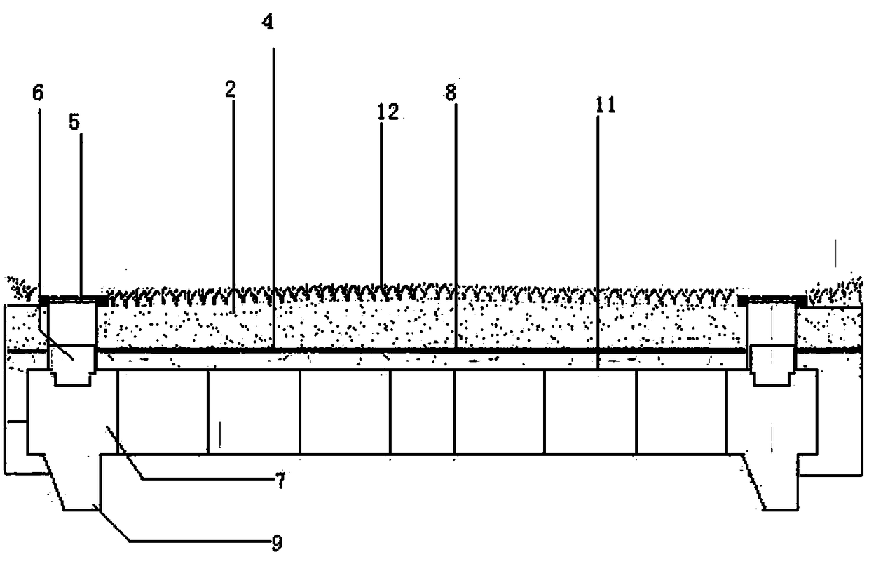
[0019] figure 1 , 2 As shown in , the rainwater drainage pipe gallery system of Zhicao Ditch includes subgrade stone 1, graded soil layer 2, geotextile 3, graded packing 4, rainwater grate 5, double-wall corrugated pipe inspection well 6, and arch storage equipment 7 , anti-seepage membrane 8, mud discharge equipment 9, roadbed stone 1 has several, several roadbed stones 1 are respectively located at the upper ends of the left and right sides of the grass-planting ditch 10, and each roadbed stone 1 has openings as water inlet holes, and the grass-planting ditch The foundation pit is excavated longitudinally at the lower end of the middle part of 10, the soil in the lower part of the grass-planting ditch 10 is compacted, and the arched storage device 7 is vertically installed in the foundation pit, and a mud discharge device 9 is installed at the lower end of the arched storage device 7 every about 30m. A double-wall corrugated pipe inspection well 6 is installed on the upper ...


PUM


Abstract

The invention discloses a vegetated ditch rainwater drainage pipe gallery system. The vegetated ditch rainwater drainage pipe gallery system comprises roadbed stones, a grading soil layer, geotechnical cloth, grading packing, rainwater perforated strainers, double-wall corrugated pipe inspection wells, arched regulation and storage equipment, an anti-seepage film and mud disposal equipment. The multiple roadbed stones are located at the upper ends of the left side and the right side of a vegetated ditch correspondingly. A foundation pit is longitudinally excavated in the lower end of the middle of the vegetated ditch. The arched regulation and storage equipment is longitudinally mounted in the foundation pit. One set of mud disposal equipment and one double-wall corrugated pipe inspectionwell are mounted at the lower end and the upper end of the arched regulation and storage equipment every multiple meters. Each rainwater perforated strainer is mounted at the upper end of the corresponding double-wall corrugated pipe inspection well. The anti-seepage film and the grading packing are sequentially laid at the upper end of tamped soil. The geotechnical cloth and the grading soil layer are sequentially laid at the upper end of the grading packing. Green plants are planted on the grading soil layer. A construction method of the vegetated ditch rainwater drainage pipe gallery systemcomprises the following steps of 1, excavation of the foundation pit; 2, construction of a geotechnical material; 3, mounting of the arched regulation and storage equipment, and laying of the gradingpacking; and 4, construction of a plantation layer. By means of the vegetated ditch rainwater drainage pipe gallery system and the construction method, rainwater can be effectively utilized.

Description

technical field [0001] The invention relates to the technical field of sponge city construction, in particular to a planting ditch rainwater drainage pipe gallery system and a construction method. Background technique [0002] Sponge city is a new generation of urban stormwater management concept, which means that the city has good "elasticity" in adapting to environmental changes and responding to natural disasters caused by rainwater. It can also be called "water elastic city"; an international general term For "low-impact development rainwater system construction"; when it rains, absorb water, store water, infiltrate water, purify water, and "release" the stored water when necessary; so as to effectively reduce the impact of rainfall on urban drainage and The purpose of efficient use of water resources. In the existing urban construction, the use of rainwater is mainly when it rains, and the rainwater directly flows into the sewer pipe gallery through the road surface, a...

Claims


Application Information

Patent Timeline
Patent Type & Authority Applications(China)
IPC IPC(8): E02D29/045
CPCE02D29/045E02D29/10
Inventor 娄锋
Owner 上海佳长环保科技有限公司
Why Eureka
Try Eureka