Beam column integral prefabricated joint with rigid template support at connecting position and construction method of beam column integral prefabricated joint

An integral prefabrication and joint technology, applied in the fields of formwork/formwork/work frame, on-site preparation of building components, construction, etc., can solve the problems of poor integrity of concrete frame structure, difficult control of weld quality, safety and quality, etc. , to achieve the effect of easy control of construction quality, convenient construction process and reduction of the number of supports

Pending Publication Date: 2018-11-23
SOUTH CHINA UNIV OF TECH
View PDF10 Cites 2 Cited by
  • Summary
  • Abstract
  • Description
  • Claims
  • Application Information

AI Technical Summary

Problems solved by technology

[0005] (1) The traditional prefabricated beam-column connection adopts mechanical sleeve grouting connection, which requires precise alignment of the steel bars protruding from the beam end and the protruding steel bars at the column nodes, which is difficult in actual operation and has hidden safety and quality risks;
[0006] (2) The welded connection of steel bars needs to transport the welding machine to the installation layer, and the quality of the weld seam during the welding process is difficult to control;
[0007] (3) The pouring strength of the beam end pouring section using ordinary concrete is low, and the integrity of the concrete frame structure is poor

Method used


Image

  • Beam column integral prefabricated joint with rigid template support at connecting position and construction method of beam column integral prefabricated joint
  • Beam column integral prefabricated joint with rigid template support at connecting position and construction method of beam column integral prefabricated joint
  • Beam column integral prefabricated joint with rigid template support at connecting position and construction method of beam column integral prefabricated joint

Examples


Embodiment Construction

[0035] The present invention will be further described in detail below in conjunction with the embodiments and the accompanying drawings, but the embodiments of the present invention are not limited thereto.

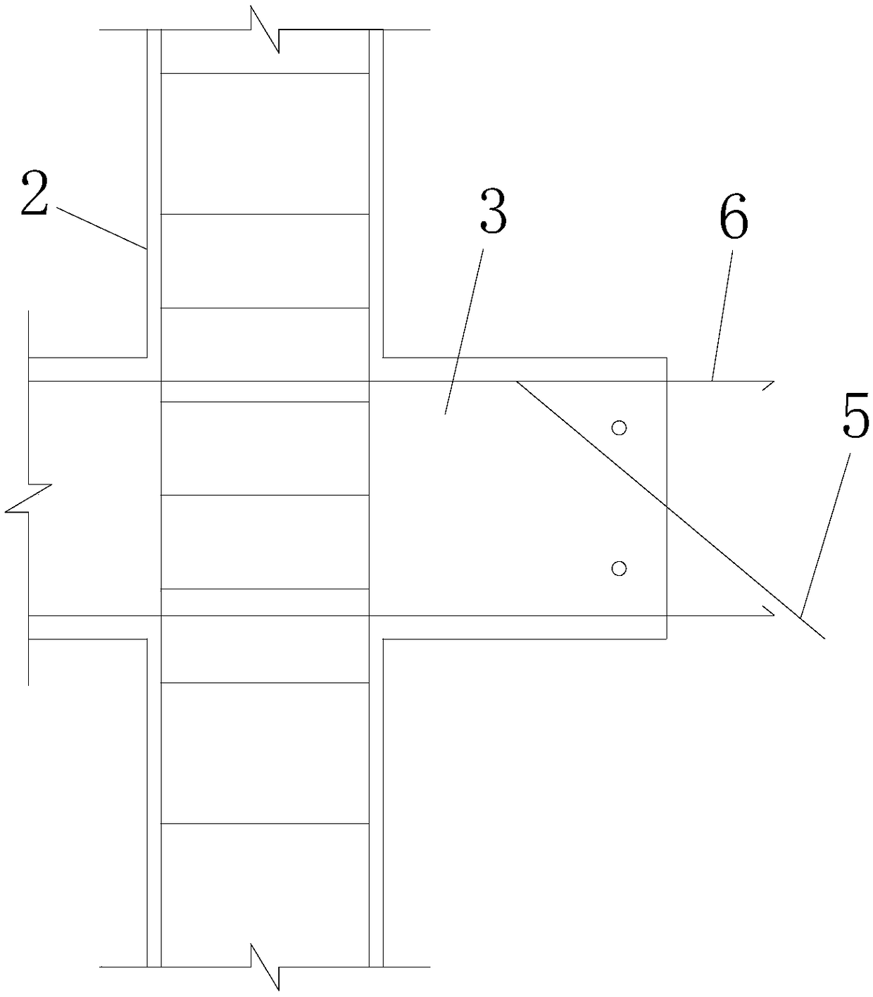
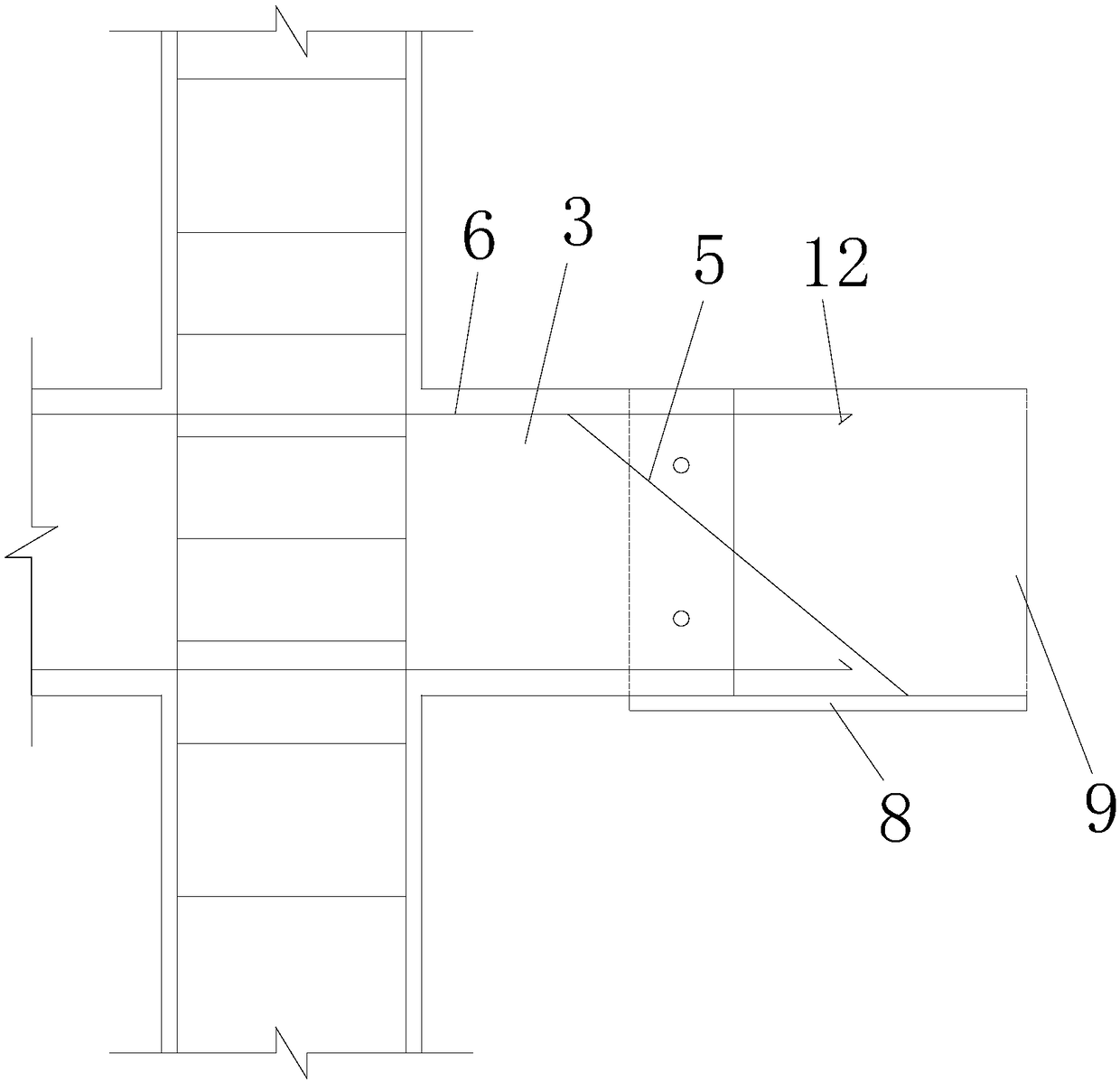
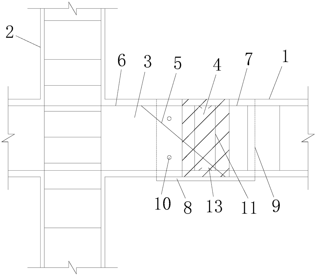
[0036] A beam-column integral prefabricated joint with rigid formwork support at the joint, including a beam 1, a steel formwork, and a prefabricated column 2 with a prefabricated joint. The prefabricated joint has a butt joint 3 that is docked with the cross beam 1, and the steel formwork and the joint 3 Fixed connection, the beam 1 is connected to the steel formwork, the steel formwork, the butt section 3 and the beam 1 are fixedly connected by pouring the connection section 4, and the butt section 3 has mitered reinforcement bars 5 and column connection reinforcement bars 6, and the mitered reinforcement bars 5 and the column connecting steel bar 6 all extend into the pouring connecting section 4, the protruding end of the mitred reinforcing bar 5 is fixedly connected ...


PUM


Abstract

The invention discloses a beam column integral prefabricated joint with a rigid template support at a connecting position and a construction method of the beam column integral prefabricated joint. Thebeam column integral prefabricated joint with the rigid template support at the connecting position comprises a cross beam, a steel template and a prefabricated column with a prefabricated joint, theprefabricated joint extends to form a butt-joint segment in butt joint with the cross beam, the steel template is fixedly connected with the butt-joint segment, the cross beam is connected to the steel template, the steel template, the butt-joint segment and the cross beam are fixedly connected through a casting connecting segment, the butt-joint segment extends to form an inclined connection steel bar and column connection steel bars, the inclined connection steel bar and the column connection steel bars extend into the casting connecting segment, the extending-out end of the inclined connection steel bar is fixedly connected with the steel template, the cross beam extends toward the casting connection segment to form beam connecting steel bars, and the beam connecting steel bars in thecasting connection segment are in overlap joint with the beam connection steel bars. The stress of the casting connection segment is smaller than that of a casting segment of a traditional beam columnjoint.

Description

technical field [0001] The invention relates to the field of construction, in particular to a beam-column integral prefabricated joint with a rigid formwork support at the joint and a construction method thereof. Background technique [0002] The prefabricated building has the advantages of improving project quality, shortening the construction period, simplifying the on-site construction process, reducing construction intensity, improving the site environment, reducing pollution, and reducing wet operations. At the same time, prefabricated buildings can effectively save resources and energy and improve material efficiency. In terms of achieving building energy efficiency and structural performance, reducing the demand for site and environmental conditions for on-site construction, reducing the number of on-site construction labor, reducing construction waste and adverse impacts of construction on the environment, facilitating information management, etc., in line with the re...

Claims


Application Information

Patent Timeline
Patent Type & Authority Applications(China)
IPC IPC(8): E04B1/58E04G13/00
CPCE04B1/58E04G13/00
Inventor 蔡健肖立韬陈庆军杨伟儒彭章锋左志亮杨春吴宏伟杨轶涵
Owner SOUTH CHINA UNIV OF TECH
Why Eureka
Try Eureka