Pulse pressure generation device for hydraulic oscillator

A hydraulic oscillator and pulse pressure technology, applied in vibration generating devices, drilling with vibration, wellbore/well components, etc., can solve the problems of increased drill string resistance, prominent gravity effect, high price, etc., and reduce tool pressure consumption. , to meet the effect of practicality and excellent work performance

Active Publication Date: 2018-11-23
河南易发石油工程技术有限公司
View PDF6 Cites 7 Cited by
  • Summary
  • Abstract
  • Description
  • Claims
  • Application Information

AI Technical Summary

Problems solved by technology

During the construction process, due to the large inclination angle and the prominent gravity effect, the resistance of lifting and lowering the drill string increases; the lower drilling tools are prone to buckling and self-locking, and the drilling tools are subjected to complex alternating stresses, resulting in a large frictional moment of the drill string; Difficulty in

Method used


Image

  • Pulse pressure generation device for hydraulic oscillator
  • Pulse pressure generation device for hydraulic oscillator
  • Pulse pressure generation device for hydraulic oscillator

Examples


Embodiment Construction

[0026] The present invention is described in further detail below by embodiment, and embodiment is only used for illustrating the present invention, does not limit the scope of the present invention.

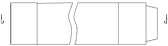
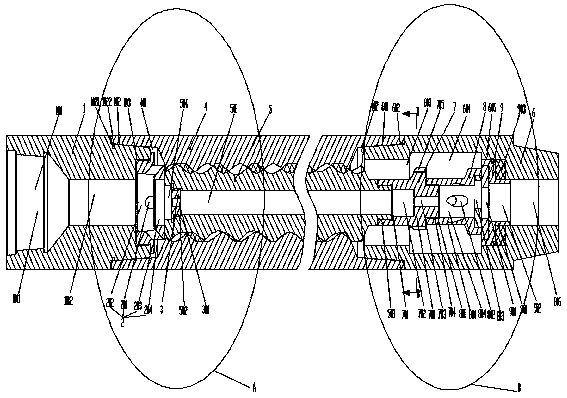
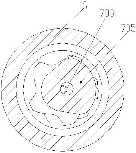
[0027] Such as Figure 1-7The pulse pressure generating device of a hydraulic oscillator shown includes an upper joint 1, a screw stator 4, a screw rotor 5 and a fixed valve joint 6, one side of the upper joint 1 is fixedly connected to one side of the screw stator 4, and the screw rotor 5 is matched. In the screw stator 4, the screw rotor 5 and the screw stator 4 are meshed and matched, and the other side of the screw stator 4 is fixedly connected to the fixed valve joint 6 side. The upper joint 1 is provided with an upper joint passage 101, and the upper joint passes through the flow channel 101. The flow channel 101 is connected to the screw rotor 5 through the upper thruster 2, the rotor nozzle 3 is set at the front of the screw rotor 5, the rear of the screw rotor 5 is conn...


PUM


Abstract

The invention relates to the field of hydraulic oscillators, in particular to a pulse pressure generation device for a hydraulic oscillator. The pulse pressure generation device comprises an upper connector, a screw stator, a screw rotor and a valve-fixing connector, one side of the upper connector is fixedly connected with one side of the screw stator, the screw rotor is matched in the screw stator and meshed with the screw stator, the other side of the screw stator is fixedly connected with one side of the valve-fixing connector, an upper connector flow passage channel runs through the upperconnector and an upper anti-thrust device and is connected with the screw rotor, a rotor nozzle is arranged in the front of the screw rotor, the rear of the screw rotor is connected with a movable valve eccentric body assembly which is connected with a movable valve body assembly, the movable valve body assembly is connected with a static valve body assembly, and the movable valve eccentric bodyassembly, the movable valve body assembly and the static valve body assembly are arranged in a valve body fixing cavity. The screw rotor is of a hollow screw structure, in this way, under the condition that a large discharge capacity is adjusted, tool pressure losses are reduced, and the requirement for site practicability of a tool is met.

Description

technical field [0001] The invention relates to the field of hydraulic oscillators, in particular to a pulse pressure generating device for hydraulic oscillators. Background technique [0002] At present, horizontal wells and extended-reach wells are the majority of drilling well types. During the construction process, due to the large inclination angle and the prominent gravity effect, the resistance of lifting and lowering the drill string increases; the lower drilling tools are prone to buckling and self-locking, and the drilling tools are subjected to complex alternating stresses, resulting in a large frictional moment of the drill string; Factors such as difficulty in torque transmission lead to severe back pressure during sliding drilling, which seriously restricts the development of drilling speed. [0003] At present, there are several ways to solve the problem of directional back pressure in construction: increase the lubricity of drilling fluid but increase the co...

Claims


Application Information

Patent Timeline
IPC IPC(8): E21B7/24E21B28/00
CPCE21B7/24E21B28/00
Inventor 彭远庆王丹李崇红杨和芳
Owner 河南易发石油工程技术有限公司
Why Eureka
Try Eureka