Rotor system and control method thereof and gas turbine generator set and control method thereof

A technology of generators and rotors, used in gas turbine installations, machines/engines, mechanical equipment, etc.

Pending Publication Date: 2018-11-23
刘慕华
View PDF0 Cites 8 Cited by
  • Summary
  • Abstract
  • Description
  • Claims
  • Application Information

AI Technical Summary

Problems solved by technology

[0005] The present invention provides a rotor system and its control method, a gas turbine generator set and it

Method used


Image

  • Rotor system and control method thereof and gas turbine generator set and control method thereof
  • Rotor system and control method thereof and gas turbine generator set and control method thereof
  • Rotor system and control method thereof and gas turbine generator set and control method thereof

Examples


Embodiment 1

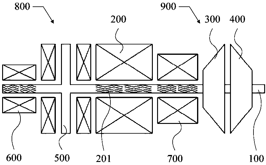
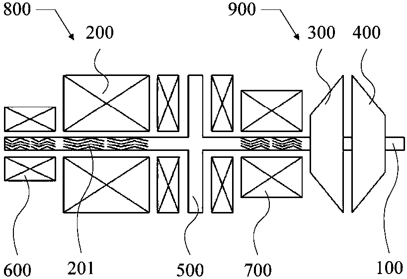
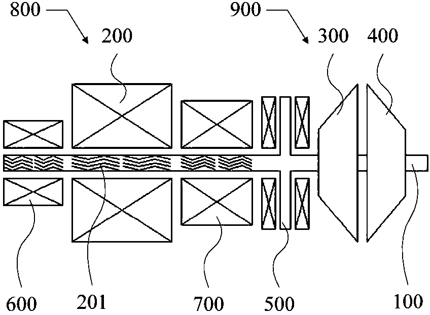
[0174] like Figure 1 to Figure 3 As shown, the rotor system includes:

[0175] The rotating shaft 100, the shaft body of the rotating shaft 100 has an integrated structure, and the rotating shaft 100 is arranged horizontally;

[0176] Motor 200, compressor 300, turbine 400, thrust bearing 500, first radial bearing 600 and second radial bearing 700 arranged on rotating shaft 100, thrust bearing 500, first radial bearing 600 and second radial bearing The bearings 700 are non-contact bearings;

[0177] And the first casing 800 and the second casing 900, the first casing 800 is connected with the second casing 900, wherein, the motor 200, the thrust bearing 500, the first radial bearing 600 and the second radial bearing 700 are all set In the first casing 800 , the compressor 300 and the turbine 400 are both arranged in the second casing 900 ;

[0178] The first radial bearing 600 is disposed on a side of the motor 200 away from the second casing 900 , and the second radial be...

Embodiment 2

[0189] like Figure 4 to Figure 6 As shown, the rotor system includes:

[0190] The rotating shaft 100, the shaft body of the rotating shaft 100 is an integral structure, and the rotating shaft 100 is vertically arranged;

[0191] Motor 200, compressor 300, turbine 400, thrust bearing 500, first radial bearing 600 and second radial bearing 700 arranged on rotating shaft 100, thrust bearing 500, first radial bearing 600 and second radial bearing The bearings 700 are non-contact bearings;

[0192] And the first casing 800 and the second casing 900, the first casing 800 is connected with the second casing 900, wherein, the motor 200, the thrust bearing 500, the first radial bearing 600 and the second radial bearing 700 are all set In the first casing 800 , the compressor 300 and the turbine 400 are both arranged in the second casing 900 ;

[0193] The first radial bearing 600 is disposed on a side of the motor 200 away from the second casing 900 , and the second radial bearing...

Embodiment 3

[0197] When the rotor system of the present application is used in a mobile device, such as an extended-range electric vehicle, when the rotor system is not working, the rotating shaft is in direct contact with the bearing. During the driving process of the car, the radial or axial movement of the rotating shaft relative to the bearing is caused by bumps or vibrations, causing wear between the rotating shaft and the bearing, which in turn affects the accuracy and life of the bearing.

[0198] Therefore, in order to solve the above problems, on the basis of other embodiments of the present invention, the rotor system of the embodiment of the present invention is provided with a locking device, and the locking device is used to lock the rotating shaft when the rotor system is not working.

[0199] In the embodiment of the present invention, the structural form and arrangement of the locking device are not unique. For ease of understanding, two implementations will be described in...


PUM


Abstract

The invention provides a rotor system and a control method thereof and a gas turbine generator set and a control method thereof. The rotor system comprises a rotating shaft, a generator, a gas compressor, a turbine, a thrust bearing, two radial bearings, a first casing and a second casing; the shaft body of the rotating shaft is of an integrated structure, and the rotating shaft is horizontally arranged or vertically arranged; the generator, the gas compressor, the turbine, the thrust bearing and the two radial bearings are arranged on the rotating shaft, and the thrust bearing and the two radial bearings are non-contact bearings; the first casing is connected to the second casing; the generator, the thrust bearing and the two radial bearings are arranged in the first casing, and the gas compressor and the turbine are arranged in the second casing; and the impeller of the gas compressor is arranged close to the impeller of the turbine in the second casing. According to the system and the control method, the machining precision and assembly precision of the gas turbine generator set are reduced, the cost is reduced, and the gas turbine generator set is suitable for engineering batchproduction.

Description

technical field [0001] The invention relates to the technical field of rotors, in particular to a rotor system and a control method thereof, a gas turbine generator set and a control method thereof. Background technique [0002] A gas turbine mainly includes three major components: a compressor, a combustor, and a turbine. After the air enters the compressor, it is compressed into high-temperature and high-pressure air, and then supplied to the combustion chamber for mixed combustion with fuel, and the high-temperature and high-pressure gas generated expands in the turbine to perform work. When the rotor rotates at high speed, the rotor will be subjected to radial force and axial force. In order to limit the radial and axial movement of the rotating shaft, radial bearings and thrust bearings need to be installed in the rotor system. Traditional radial bearings and thrust bearings are both contact bearings. As the rotor speed increases, especially when the rotor speed excee...

Claims


Application Information

Patent Timeline
IPC IPC(8): F01D5/02F02C7/06F02C6/00F02C9/00
CPCF01D5/02F02C6/00F02C7/06F02C9/00
Inventor 靳普
Owner 刘慕华
Why Eureka
Try Eureka