
Device for controlling an air system regulator for an internal combustion engine

An air system and air control technology, applied to internal combustion piston engines, electrical control, combustion engines, etc., can solve the problems of motor vehicle acceleration and achieve the effect of ensuring combustion and safe combustion

Active Publication Date: 2018-11-23
ROBERT BOSCH GMBH
View PDF13 Cites 0 Cited by
  • Summary
  • Abstract
  • Description
  • Claims
  • Application Information

AI Technical Summary

Problems solved by technology

In the worst case, this would lead to a no longer controllable acceleration of the motor vehicle

Method used


Image

  • Device for controlling an air system regulator for an internal combustion engine
  • Device for controlling an air system regulator for an internal combustion engine
  • Device for controlling an air system regulator for an internal combustion engine

Examples


Embodiment Construction

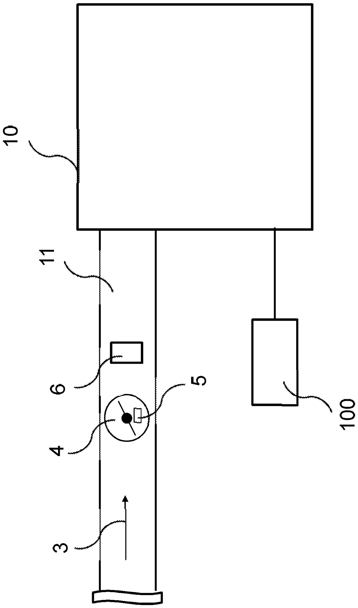
[0019] figure 1 A schematic illustration of an air system regulator 5 for an internal combustion engine 10 and a controller 100 are shown. The controller 100 includes a storage medium not otherwise shown. Internal combustion engine 10 is preferably used in a motor vehicle. The air system regulator 5 is preferably a throttle valve 4 . The internal combustion engine 10 is supplied with air 3 via an intake manifold 11 . In the intake duct 11 , the following devices are arranged in the flow direction of the air 3 : a throttle valve 4 with a position sensor 5 and a pressure sensor 6 . The throttle valve 4 can be switched to different positions, so that the cross section of the intake manifold 11 can be infinitely adjusted between fully closed and fully open by means of the throttle valve 4 . Position sensor 6 here detects the position of throttle valve 4 and communicates this position to controller 100 . From this position, the controller 100 can determine the opening angle of...


PUM


Abstract

A device for controlling an air system regulator (5) for use in an internal combustion engine (10) is provided for determining an ambient air density, wherein the device comprises a machine readable storage medium storing a command on the storage medium, the command causing the following when implemented by the computer: the computer performs the method in the following steps: a) determining a first value of the ambient air density, wherein when the decrease in the first value exceeds the maximum allowable, changes in the first value is limited; (b) controlling the air system regulator (5) bydepending on changes in the first value.

Description

technical field [0001] The invention relates to a device for controlling an air system regulator for an internal combustion engine, which device is designed to carry out such a method. Background technique [0002] In internal combustion engines with an electrically actuated throttle valve, the air supplied to the engine must be limited to a plausible control value for safety reasons in order to prevent undesired acceleration by the driver. Such a guarantee is achieved as a standard by means of a throttle-based limitation, for example by predefining a maximum opening angle for the throttle. For this limitation, the opening of the throttle valve must then be corrected towards a lower ambient air density as a function of the ambient air density and the ambient temperature, since the volume of air supplied for combustion must increase as the air density decreases. [0003] In systems with only one sensor for measuring the ambient air density, abrupt changes in the ambient air ...

Claims


Application Information

Patent Timeline
Patent Type & Authority Applications(China)
IPC IPC(8): F02D41/00
CPCF02D41/0002F02D2200/101F02D11/107F02D2200/0406F02D2200/704Y02T10/40
Inventor R.瓦克罗A.比特纳F.瓦格纳H.勒施T.卡莱霍夫
Owner ROBERT BOSCH GMBH
Learn More