Three-phase separator, oil and gas well testing and measuring system and combustion control method of oil and gas well testing and measuring system

A technology of three-phase separator and metering system, which is applied in the field of three-phase separator and oil and gas well test metering system and its combustion control, and can solve the requirements of large volume of three-phase separation metering equipment, large volume of three-phase separation equipment and service conditions Advanced problems, to achieve the effect of simple structure, small footprint and low cost

Active Publication Date: 2017-11-17
CHINA FRANCE BOHAI GEOSERVICES
View PDF4 Cites 3 Cited by
  • Summary
  • Abstract
  • Description
  • Claims
  • Application Information

AI Technical Summary

Problems solved by technology

[0007] In order to solve the technical problems of large volume, high cost and complicated operation of the three-phase separation equipment, the present invention designs and develops a three-phase separator
[0008] In order to solve the technical problems of large volume of three-phase separation metering equipment, high requirements for use conditions and low precision in oil and gas field testing, the present invention designs and develops an oil and gas well testing and metering system

Method used


Image

  • Three-phase separator, oil and gas well testing and measuring system and combustion control method of oil and gas well testing and measuring system
  • Three-phase separator, oil and gas well testing and measuring system and combustion control method of oil and gas well testing and measuring system
  • Three-phase separator, oil and gas well testing and measuring system and combustion control method of oil and gas well testing and measuring system

Examples


Embodiment Construction

[0077] The present invention will be further described in detail below in conjunction with the accompanying drawings, so that those skilled in the art can implement it with reference to the description.

[0078] The invention may be embodied in many different forms and should not be construed as limited to the embodiments set forth herein; rather, these embodiments are provided so that this disclosure will be thorough and complete. In the drawings, the size and relative sizes of structures and regions may be exaggerated for clarity.

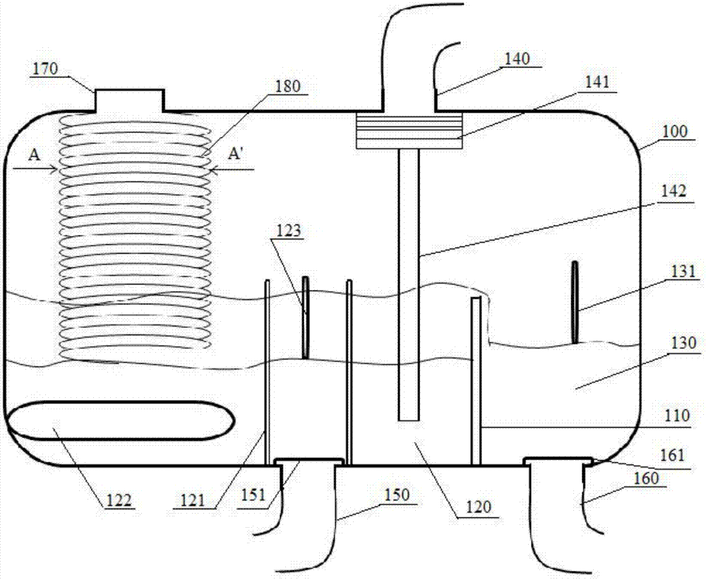
[0079] Such as Figure 1-2 As shown, the present invention provides a three-phase separator, comprising: a housing 100, the housing surrounds and forms a separation chamber; an overflow partition 110 is arranged in the separation chamber, and divides the separation chamber into The first cavity 120 and the second cavity 130, the height of the overflow partition 110 can be adjusted; the exhaust port 140 is arranged on the top of the housing 100; ...


PUM


Abstract

The invention discloses a three-phase separator. The three-phase separator comprises a shell body, an overflowing baffle, a gas outlet, liquid outlets, a gas-liquid inlet and a classification rotating blade, wherein a separating cavity is defined by the shell body, the overflowing baffle is arranged in the separating cavity and divides the separating cavity into a first cavity body and a second cavity body, and the height of the overflowing baffle can be adjusted; the gas outlet is formed in the top of the shell body, the liquid outlets comprise a water outlet and an oil outlet which are formed in the bottoms of the first cavity body and the second cavity body correspondingly, and the gas-liquid inlet is formed in the upper portion of the shell body; and the classification rotating blade is arranged below the gas-liquid inlet, communicates with the gas-liquid inlet and goes deep into the inner portion of the first cavity body. According to the three-phase separator, the structure is simple, operation is convenient, and the separating efficiency is high. The invention further provides an oil and gas well testing and measuring system and a combustion control method thereof. A Vx multiphase flowmeter is adopted, the surface flow rate of underground sample liquid is simply and rapidly measured, by using the three-phase separator, the underground sample liquid is separated efficiently, finally, the size of a fuel nozzle of a PID control combustor and the pressure of air compressed by an air compressor are blurred, and combustion treatment is more sufficient and safer.

Description

technical field [0001] The invention relates to the technical field of oil and gas field testing and metering, and more specifically, the invention relates to a three-phase separator, an oil and gas well testing and metering system and a combustion control method thereof. Background technique [0002] Before the development of oil and gas wells, it is necessary to test oil first, that is, to induce downhole oil and gas to flow to the surface, and to measure oil, gas, and water, so as to provide a basis for evaluating the production capacity of oil and gas wells and formulating development plans. At present, in the development and testing process of oil and gas wells, three-phase separation is used for conventional metering, and the equipment is bulky, heavy, and occupies a large area. In addition, there are the following disadvantages: [0003] 1. Based on the principle of gravity separation, the three-phase separator cannot handle emulsion and heavy oil. It needs to be hea...

Claims


Application Information

Patent Timeline
IPC IPC(8): E21B43/34E21B47/00F23N1/00
CPCE21B43/34E21B47/00F23N1/002
Inventor 林炳南徐凤阳关利军林炳龙高科超李纪智
Owner CHINA FRANCE BOHAI GEOSERVICES
Why Eureka
Try Eureka