Ground torch grading emission control device and method

A technology for ground flare and emission control

Inactive Publication Date: 2019-03-05
SINOPEC GUANGZHOU ENG +1
View PDF4 Cites 3 Cited by
  • Summary
  • Abstract
  • Description
  • Claims
  • Application Information

AI Technical Summary

Problems solved by technology

Option 1 is easy to operate, but there are risks of inaccurate pressure values ​​at the pressure measurement points, false reports of pressure gauges, and failures, resulting in system pressure and failure to discharge in time; Option 2 has pressure loss due to the pressure loss of the graded regulating valve or switch valve itself and the branch venting pipeline , during the opening or closing process of the valve, the pressure value at the pressure measuring point will fluctuate frequently, making the control valve unable to perform stable control, resulting in unstable combusti

Method used


Image

  • Ground torch grading emission control device and method

Examples


Embodiment 1

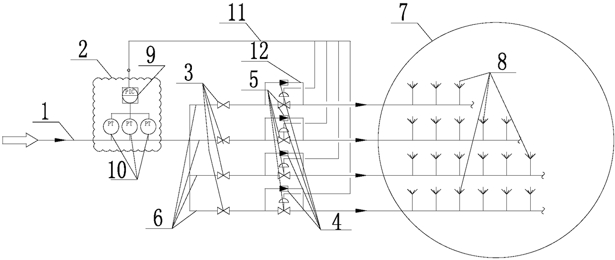
[0025] A ground torch staged emission control device, comprising a venting main pipe, a staged discharge system, a staged control system, a burner and a ground torch combustion furnace, one end of the staged discharge system communicates with the main pipeline, and the other end communicates with the burner, and the staged control system communicates with the burner The graded discharge system is connected with the main pipeline, and the burner is installed in the ground torch combustion furnace. The graded discharge system includes the main pipeline, sub-pipes, pressure control valves, and shut-off valves. The main pipeline is connected with the sub-pipes, and the sub-pipes are equipped with pressure control valves and Shut-off valve, the shut-off valve is located at the front end of the pressure control valve, and the hierarchical control system includes pressure control valves, pressure detection and pressure transmitters and signal lines, the pressure detection and pressure ...

Embodiment 2

[0027] A ground torch staged emission control device, comprising a venting main pipe, a staged discharge system, a staged control system, a burner and a ground torch combustion furnace, one end of the staged discharge system communicates with the main pipeline, and the other end communicates with the burner, and the staged control system communicates with the burner The graded discharge system is connected with the main pipeline, and the burner is installed in the ground torch combustion furnace. The graded discharge system includes the main pipeline, sub-pipes, pressure control valves, and shut-off valves. The main pipeline is connected with the sub-pipes, and the sub-pipes are equipped with pressure control valves and Shut-off valve, the shut-off valve is located at the front end of the pressure control valve, and the hierarchical control system includes pressure control valves, pressure detection and pressure transmitters and signal lines, the pressure detection and pressure ...

Embodiment 3

[0029] A ground flare discharge control method, characterized in that: 5 pressure signal gauges on the main pipeline, when the 4 or 5 pressure signal values ​​on the main pipeline reach the opening and closing control values ​​of the regulating valves on the sub-pipelines, the control valves on the sub-pipelines On and off.


PUM


Abstract

The invention discloses a ground torch grading emission control device and method. The ground torch grading emission control device comprises an empty main pipe, a grading emission system, a grading control system, a burner and a ground torch combustion furnace, wherein one end of the grading emission system communicates with a main pipeline, the other end of the grading emission system communicates with the burner, the grading control system communicates with the grading emission system and the main pipeline, and the burner is arranged in the ground torch combustion furnace. According to theground torch grading emission control device, the mutual effect of all levels of emission systems can be avoided, smokeless combustion can be realized under the pressure, automatic switching can be realized when any level fails, and the safety is high.

Description

technical field [0001] The invention belongs to the field of combustible gas discharge in petrochemical enterprises, and in particular relates to a ground flare staged discharge control device. Background technique [0002] The combustible gas treatment device is an indispensable safety emission combustion facility for the relevant production devices of petrochemical enterprises. Timely, safe and reliable emission and combustion; complete combustion, low noise, meeting environmental protection requirements; low operating costs, small protection radius, are the most basic requirements for the flare gas treatment device. The ground torch has the characteristics of small heat radiation, convenient maintenance, light pollution to the surrounding environment, small footprint, and can realize smokeless combustion. Like the elevated torch, the ground torch system is a new type of smokeless, low-noise and environmentally friendly torch Gas treatment devices are gradually being used...

Claims


Application Information

Patent Timeline
IPC IPC(8): F23G7/06F23G5/50
CPCF23G7/06F23G5/50F23G2207/102
Inventor 曾波徐兴文何龙辉王惠勤李占杰王文昊谢伟峰
Owner SINOPEC GUANGZHOU ENG
Why Eureka
Try Eureka