Surge device for air drilling

a technology of air drilling and shock device, which is applied in the direction of drilling rods, drilling pipes, borehole/well accessories, etc., can solve the problems of flammable gas leakage, failure of blooie lines, and inability to hold up well

Inactive Publication Date: 2006-07-11
FINCHUM RAY A
View PDF14 Cites 3 Cited by
  • Summary
  • Abstract
  • Description
  • Claims
  • Application Information

AI Technical Summary

Benefits of technology

[0011]The present invention is a surge device for use with drilling equipment used in air drilling a well. The surge device inserts in the flow or blooie line and contains connectors for attaching two surge lines and contains a blowdown or vent line for bleeding off pressure from the well bore. The surge device is provided with a tapered chamber into which the two surge lines and the blow down line enter the surge device. This tapered chamber is hollow and is provided with a flange at each end of the chamber. The chamber is provided with a first flange on a narrow end of the tapered chamber that can be removably bolted to a flange provided on the blooie line so that the tapered end of the tapered chamber attaches to the downstream end of the blooie line. The downstream end of the blooie line, in turn, connects to the reserve pit. Normally either a flare or pilot light is provided at the reserve pit to safely burn any entrained flammable gases that flow to the reserve pit via the blooie line.

Problems solved by technology

The problem with the current method of installing these pipes to the blooie line is that due to the highly abrasive nature of the material that is passing through the blooie line, the three pipes and their connection to the blooie line do not hold up well and are often the point at which abrasion causes a failure in the blooie line.
This can result in downtime to fix the leak and can result leakage of flammable gas that can explode or catch on fire.
Another problem with the current method of installing the two pipes to the blooie line that will serve as the surge lines is that the openings in the blooie line to which the angled ends of the pipes are welded is an elongated oval shape.
This elongated oval shape orifice does not function well to direct air in a downstream orientation within the blooie line as the air flows into the blooie line from the surge lines.
If the surge lines are not effective in pulling a vacuum on the well, flammable gas originating in the well could travel upward through the wellhead where it could explode or ignite, resulting in disastrous injury to workmen and damage to the drilling rig.

Method used


Image

  • Surge device for air drilling
  • Surge device for air drilling
  • Surge device for air drilling

Examples


Embodiment Construction

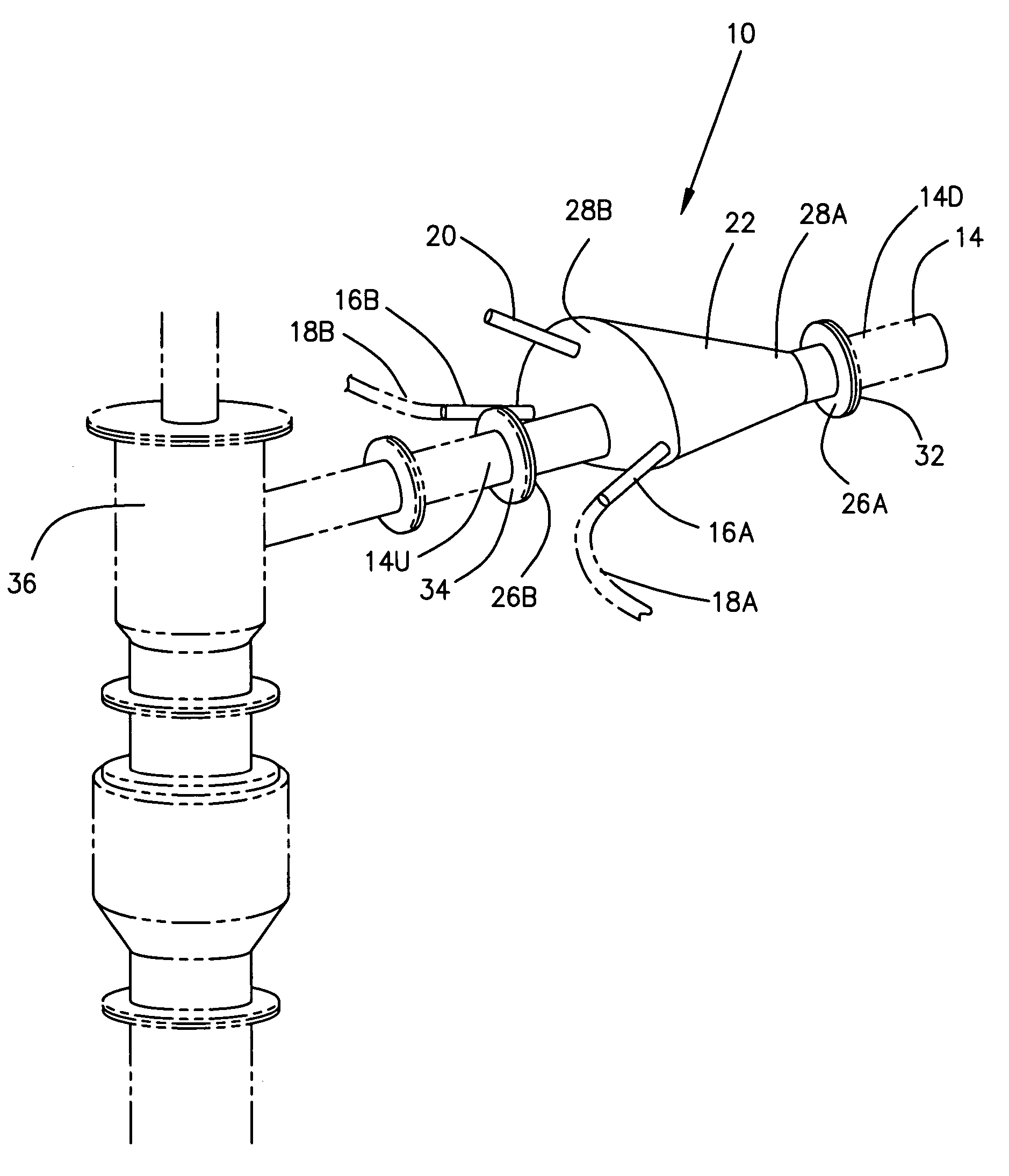
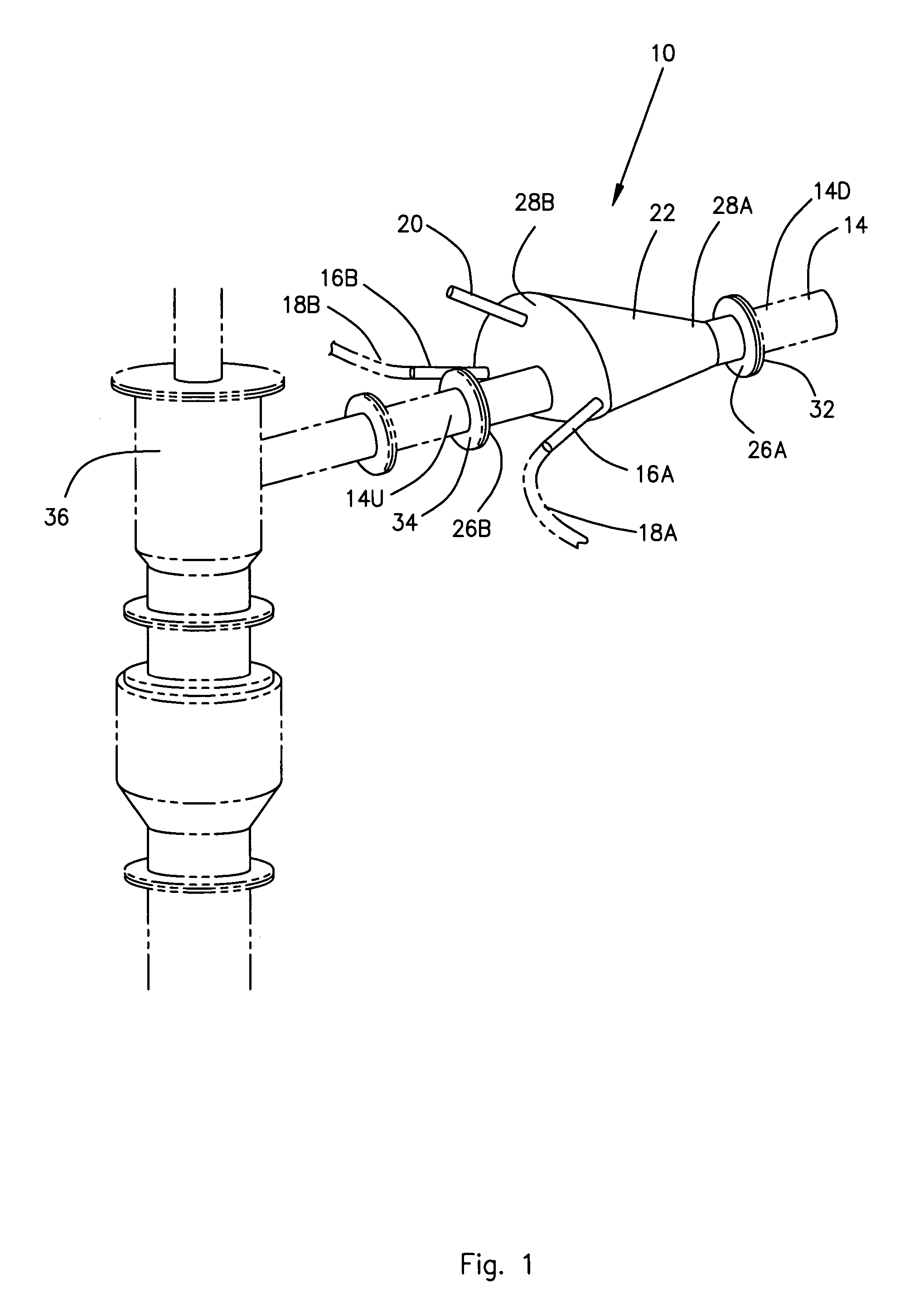
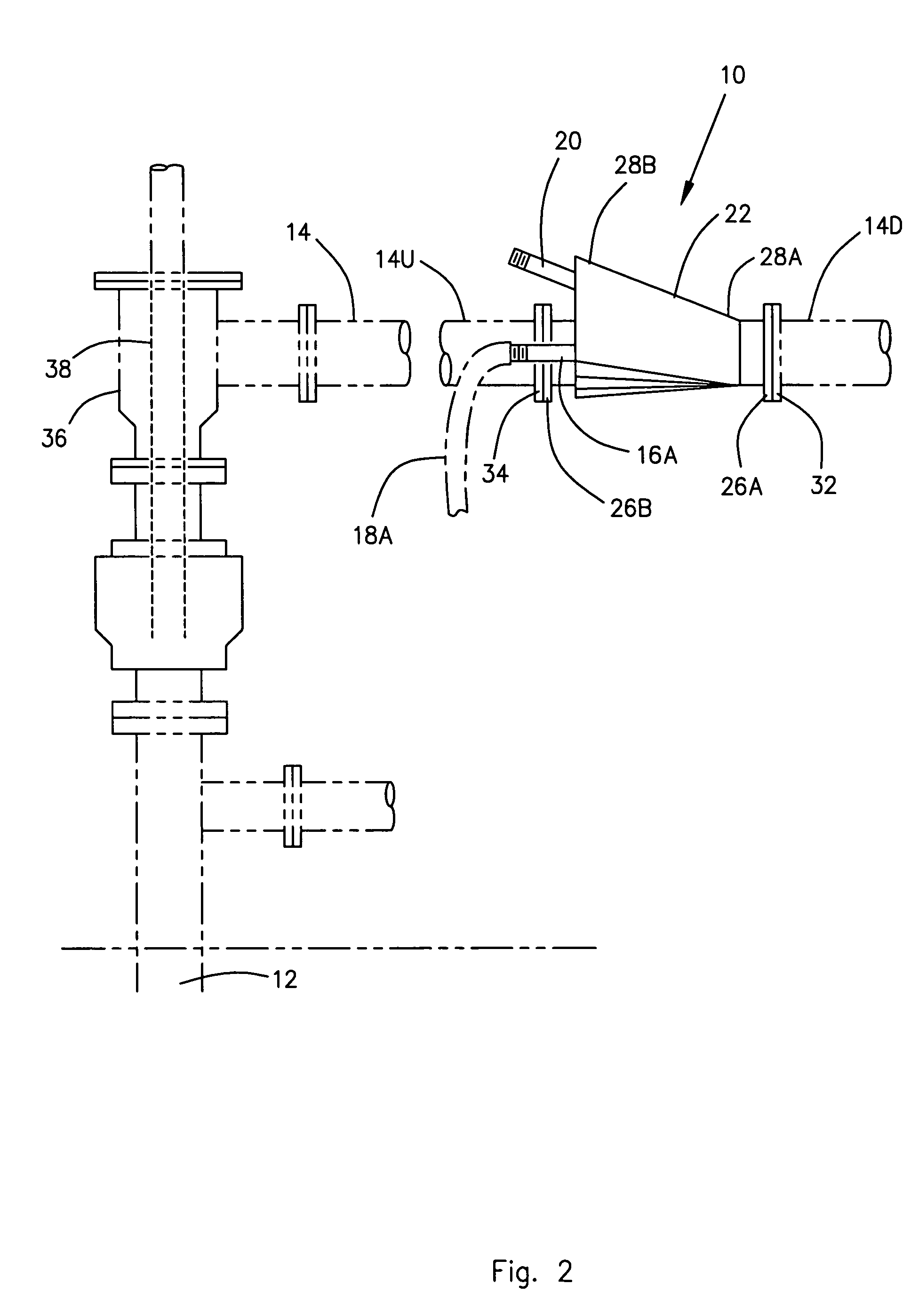
[0020]Referring now to the drawings, and initially to FIGS. 1 and 2, there is illustrated a surge device 10 constructed in accordance with a preferred embodiment of the present invention. FIGS. 1 and 2 show the surge device 10 in use with drilling equipment, shown in outline, that is used in air drilling a well 12. The surge device 10 is installed in a flow or blooie line 14 and it contains connectors 16A and 16B for attaching the two surge lines 18A and 18B to the surge device 10 and also contains a blowdown or vent line 20 for bleeding off pressure from the well 12. The surge lines 18A and 18B are also called air vacuum lines because they supply air to the blooie line 14 which in turn creates a vacuum on the well 12. The surge device 10 is provided with walls 22 that form an internal, hollow tapered chamber 24 into which the connectors 16A and 16B for the two surge lines 18A and 18B and the blow down line 20 enter the surge device 10.

[0021]The surge device 10 is provided with a fl...


PUM


Abstract

A surge device providing a vent for bleeding pressure off an air drilled well and providing connectors for surge lines in the blooie line. The surge device has a hollow, abrasion resistant, tapered chamber into which two surge lines and the blow down line enter the surge device. The device is provided with a flange at each end of the chamber for attaching the device into a blooie line with the narrow end of the tapered chamber attached to the downstream end of the blooie line and an enlarged end of the tapered chamber attached to the upsteam end of the blooie line. An abrasion resistant shield pipe penetrating the enlarged end of the tapered chamber and extending into the tapered chamber a sufficient distance to serve as a shield for the terminal ends of the surge lines and the blow down line.

Description

BACKGROUND OF THE INVENTION[0001]1. Field of the Invention[0002]The present invention relates to a surge device for use with equipment used in air drilling a well. More specifically, the present invention is a surge device that inserts in the flow or blooie line and contains connectors for attaching two surge lines and contains a blowdown or vent line for bleeding off pressure from the well bore.[0003]2. Description of the Related Art[0004]During air drilling of a well, the workmen will need to break the string of drill pipe frequently to make up new connections in the drill string. Before workman can safely break the string, they must first insure that pressure has been bled off of the drill pipe so that the pressure will not blow out at them as they break the string. Also before they can safely break the string, they must insure that flammable gas is constantly removed from the well while they are making the connection so that flammable gas from the well does not flow onto the dri...

Claims


Application Information

Patent Timeline
Patent Type & Authority Patents(United States)
IPC IPC(8): E21B21/16E21B21/01
CPCE21B21/16E21B21/01
Inventor FINCHUM, RAY A.
Owner FINCHUM RAY A
Why Eureka
Try Eureka