Regeneration type radiant tube gas combustor for medium-low-heat-value fuel gas

A regenerative radiant tube and burner technology, which is applied to gas fuel burners, burners, combustion methods, etc., can solve the problems of affecting the preheating effect, different temperatures of air and gas, and environmental pollution, etc., so as to increase the effective exchange rate Heat area, prevent local high temperature, and prolong service life

Pending Publication Date: 2018-08-14
赵升智 +1
View PDF0 Cites 1 Cited by
  • Summary
  • Abstract
  • Description
  • Claims
  • Application Information

AI Technical Summary

Problems solved by technology

[0003] However, the existing regenerative radiant tube burners mainly preheat the air, which causes the temperature difference between the air and the gas, which affects the preheating effect. In addition, the existing regenerative radiant tube burners still have radiant tubes The lack of protection in the high-temperature area, the local high temperature of the radiant tube affects the service life of the radiant tube, and the existing regenerative radiant tube burner directly discharges the flue gas after combustion, and the residence time in the radiant tube is relatively short. High nitrogen oxide content, more serious environmental pollution

Method used


Image

  • Regeneration type radiant tube gas combustor for medium-low-heat-value fuel gas
  • Regeneration type radiant tube gas combustor for medium-low-heat-value fuel gas
  • Regeneration type radiant tube gas combustor for medium-low-heat-value fuel gas

Examples


Embodiment Construction

[0024] The following will clearly and completely describe the technical solutions in the embodiments of the present invention with reference to the accompanying drawings in the embodiments of the present invention. Obviously, the described embodiments are only some, not all, embodiments of the present invention. Based on the embodiments of the present invention, all other embodiments obtained by persons of ordinary skill in the art without making creative efforts belong to the protection scope of the present invention.

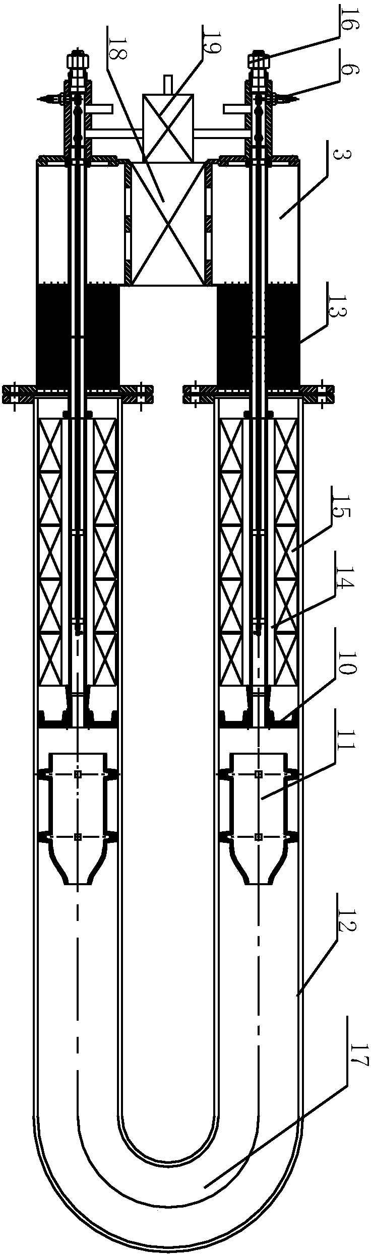
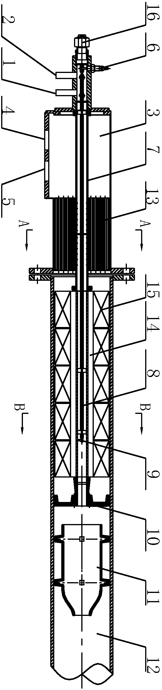
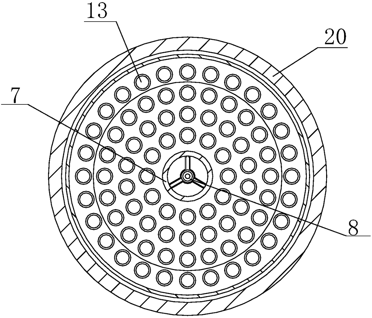
[0025] see Figure 1 to Figure 4 , the technical solution of the present invention:

[0026] A medium and low calorific value gas regenerative radiant tube gas burner, comprising two combustion devices and a radiant tube 12, the two combustion devices are installed at the end of the radiant tube 12, the combustion device includes a gas inlet 1, an air The inlet 2 and the gas passage 7, the gas inlet 1 and the air inlet 2 communicate with the gas passage 7, th...


PUM


Abstract

The invention provides a regeneration type radiant tube gas combustor for medium-low-heat-value fuel gas. According to the regeneration type radiant tube gas combustor, fuel gas inlets and air inletscommunicate with fuel gas channels, the fuel gas channels extend into a radiant tube, central ignition rods are arranged in the fuel gas channels, one ends of the central ignition rods are connected to sparking plugs arranged on combustion devices, the other ends of the central ignition rods are connected to ignition electrodes arranged in the fuel gas channels, disc-shaped nozzles and combustioncylinders are arranged in the radiant tube, the disc-shaped nozzles are arranged at outlets of the fuel gas channels, flue gas cavities are formed between the fuel gas inlets and the end part of the radiant tube, tubular heat exchangers are further arranged between the fuel gas inlets and the end part of the radiant tube, dividing wall type regenerators are arranged on the outer sides, extending into the radiant tube, of the fuel gas channels, and regenerator bodies fill between the dividing wall type regenerators and the inner side of the radiant tube. The regeneration type radiant tube gas combustor has the advantages that the fuel gas channels adopt tubular heat exchanger+dividing wall type regenerator structures, so that the effective heat exchange area can be increased, double preheating of air and the fuel gas can be achieved, the thermal equivalent is balanced, especially for medium-low-heat-value fuel gas, and the preheating effect can be better.

Description

technical field [0001] The invention relates to the technical field of burners, in particular to a medium-low calorific value gas regenerative radiant tube gas burner. Background technique [0002] Regenerative radiant tubes apply high-temperature air combustion technology to gas radiant tubes, mainly using combustible gases such as coal gas as fuel, and the combustion air or gas is preheated to a high temperature above 900°C, and then enters the radiant tube for mixed combustion. Since the air or gas is preheated, for 800~3000kcal / N·m 3 The low calorific value gas can also burn stably, so the regenerative radiant tube burner has a wide range of fuel adaptability. It has the advantages of high combustion efficiency, stable operation, reliable and simple equipment, etc., and is widely used in various heat treatment furnaces and continuous heating furnaces in petrochemical, metallurgical and other industries. [0003] However, the existing regenerative radiant tube burners m...

Claims


Application Information

Patent Timeline
IPC IPC(8): F23D14/12F23D14/48
CPCF23D14/12F23D14/48Y02E20/34
Inventor 赵升智冯连群
Owner 赵升智
Why Eureka
Try Eureka