Valve buffer device
A buffer device and valve technology, which is applied in the field of valves, can solve the problems of affecting the normal use of valves, reducing the service life of valves, and unreliable performance, so as to achieve reliable performance, prevent direct impact, and facilitate control
- Summary
- Abstract
- Description
- Claims
- Application Information
AI Technical Summary
Problems solved by technology
Method used
Image
Examples
Embodiment 1
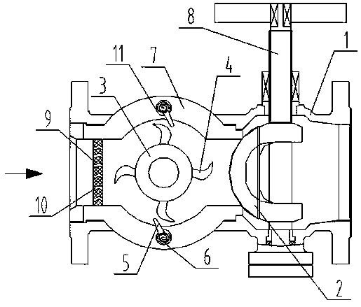
[0024] Such as figure 1 As shown, the valve buffer device includes a valve body 1, and the valve body 1 is provided with a valve core 2, a valve seat 7 and a valve stem 8, and the valve stem 8 is connected to the valve core 2, and the valve core 2 and the valve seat 7 corresponding to the inner cavity, the valve seat 7 is provided with an elastic mold 9 and a roller 3 in turn from left to right, the elastic mold 9 is covered with a plurality of through holes 10, and the roller 3 is evenly distributed There are a plurality of impellers 10, the inner wall of the valve seat 7 is provided with a roller 11, the roller 11 is connected to the valve seat 7 through a shaft, the torsion spring 6 is directly connected to the roller 11 and the valve seat 7, A rocker 5 is arranged on the roller 11 .
[0025] The direction of the arrow in the drawing is the direction in which the liquid enters the valve body 1. After the liquid enters the valve body 1, it first impacts on the elastic mold ...
Embodiment 2
[0027] Such as figure 1 As shown, the valve buffer device includes a valve body 1, and the valve body 1 is provided with a valve core 2, a valve seat 7 and a valve stem 8, and the valve stem 8 is connected to the valve core 2, and the valve core 2 and the valve seat 7 corresponding to the inner cavity, the valve seat 7 is provided with an elastic mold 9 and a roller 3 in turn from left to right, the elastic mold 9 is covered with a plurality of through holes 10, and the roller 3 is evenly distributed There are a plurality of impellers 10, the inner wall of the valve seat 7 is provided with a roller 11, the roller 11 is connected to the valve seat 7 through a shaft, the torsion spring 6 is directly connected to the roller 11 and the valve seat 7, A rocker 5 is arranged on the roller 11 .
[0028] The through holes 9 are curved and wavy holes.
[0029] The rocking bar 5 is in an inclined state, and the top is an arc structure.
[0030] The direction of the arrow in the drawin...
Embodiment 3
[0035] Such as figure 1 As shown, the valve buffer device includes a valve body 1, and the valve body 1 is provided with a valve core 2, a valve seat 7 and a valve stem 8, and the valve stem 8 is connected to the valve core 2, and the valve core 2 and the valve seat 7 corresponding to the inner cavity, the valve seat 7 is provided with an elastic mold 9 and a roller 3 in turn from left to right, the elastic mold 9 is covered with a plurality of through holes 10, and the roller 3 is evenly distributed There are a plurality of impellers 10, the inner wall of the valve seat 7 is provided with a roller 11, the roller 11 is connected to the valve seat 7 through a shaft, the torsion spring 6 is directly connected to the roller 11 and the valve seat 7, A rocker 5 is arranged on the roller 11 .
[0036] The through holes 9 are curved and wavy holes.
[0037] The rocking bar 5 is in an inclined state, and the top is an arc structure.
[0038] The upper and lower inner sides of the v...
PUM
 Abstract
Description
Claims
Application Information
 - R&D
- Intellectual Property
- Life Sciences
- Materials
- Tech Scout
- Unparalleled Data Quality
- Higher Quality Content
- 60% Fewer Hallucinations
Browse by: Latest US Patents, China's latest patents, Technical Efficacy Thesaurus, Application Domain, Technology Topic, Popular Technical Reports.
© 2025 PatSnap. All rights reserved.Legal|Privacy policy|Modern Slavery Act Transparency Statement|Sitemap|About US| Contact US: help@patsnap.com

