Solar switch cabinet and application method thereof

A technology of switchgear and solar energy, applied in substation/switch layout details, substation/switchgear cooling/ventilation, electrical components, etc., can solve problems such as user inconvenience, condensation, moisture, etc., to prevent safety reduction, Reduce operating costs and ensure stable work

Active Publication Date: 2018-11-23
JIANGSU JINLI ELECTRIC
View PDF8 Cites 4 Cited by
  • Summary
  • Abstract
  • Description
  • Claims
  • Application Information

AI Technical Summary

Problems solved by technology

When the original switchgear dissipates heat inside, and when the temperature difference between the cabinet and the outside is too large, condensation may occur inside the switchgear, which may cause the switchgear to be affected by condensation, thereby reducing the safety of the switchgear. bring inconvenience
Moreover, when the existing switchgear is used outdoors, an external power supply is generally used to drive the cooling load, which does not conform to the trend of energy conservation and environmental protection, and is easily affected by rainwater and damp, which further reduces the safety and service life of the switchgear.

Method used


Image

  • Solar switch cabinet and application method thereof
  • Solar switch cabinet and application method thereof

Examples


Embodiment

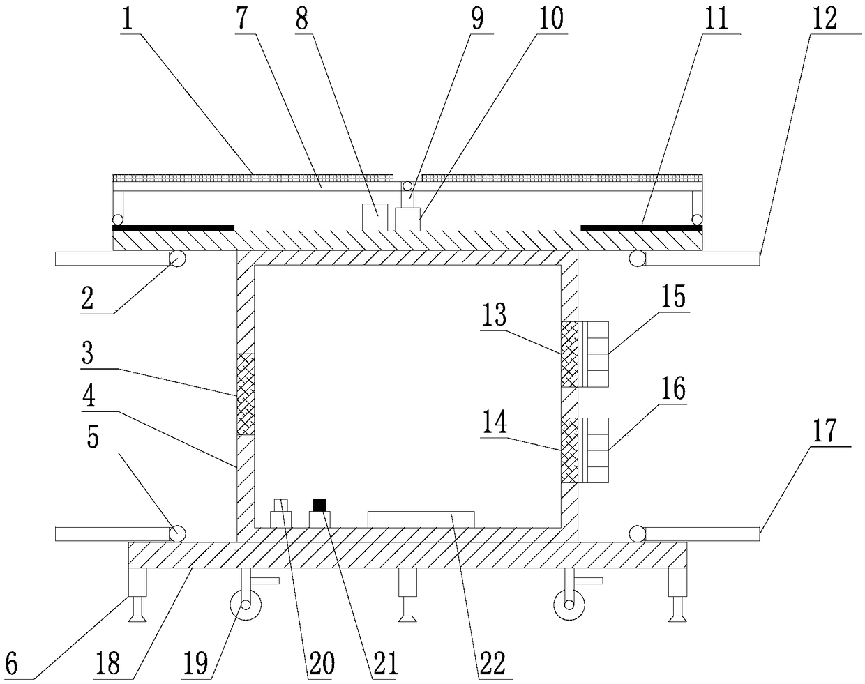
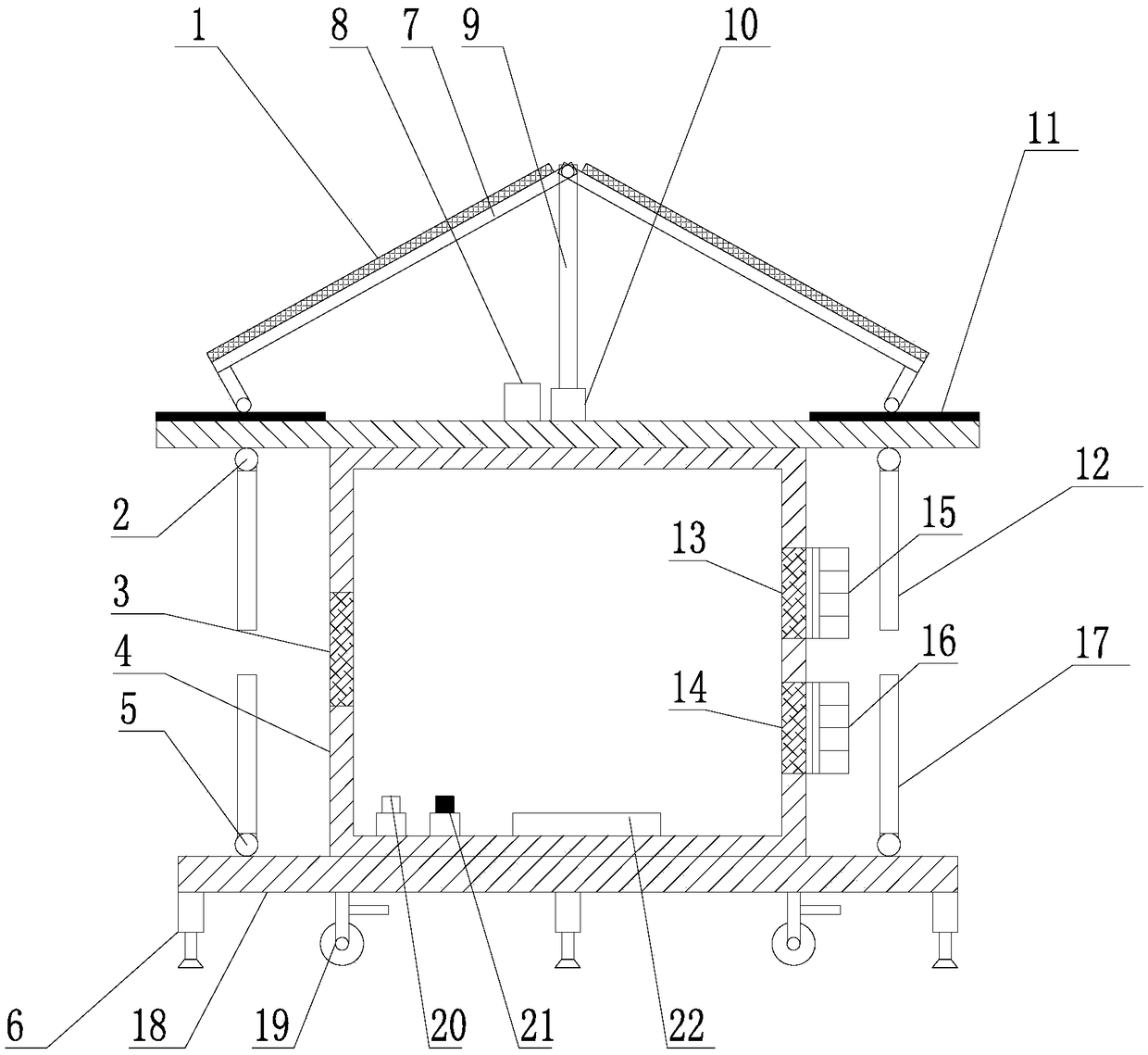
[0033] The solar switch cabinet of the present embodiment, as figure 1 with 2 As shown, it includes a rectangular base 18, a switchgear box 4 and a top cover 23, the switchgear box 4 is arranged on the upper end of the rectangular base 18, the top cover 23 is arranged on the upper end of the switchgear box 4, and the switchgear box 4 One side wall is provided with a first air inlet 13 and a second air inlet 14, an axial flow fan 15 is installed at the first air inlet 13, an ion fan 16 is installed at the second air inlet 14, and the switch cabinet box 4 is connected to the second air inlet. An air outlet 3 is provided on a side wall opposite to the first air inlet 13 and the second air inlet 14;

[0034] The lower end of the top cover 23 is respectively hinged with an upper rain shield 12 near the outer sides of the switch cabinet box 4, and the upper rain shield 12 and the top cover 23 are hinged with a first rotating motor 2 for driving the upper rain shield 12 along the hi...


PUM


Abstract

The invention relates to a solar swith cabinet and an application method thereof, and belongs to the technical field of power distribution equipment. The solar switch cabinet comprises a rectangular base, a switch cabinet box body and a top cover, the switch cabinet box body is arranged at the upper end of the rectangular base, and the top cover is arranged at the upper end of the switch cabinet box body; an upper rain baffle is respectively hinged to the lower end of the top cover near the periphery outside of the switch cabinet box body, and a lower rain baffle is respectively hinged to theupper end of the rectangular base near the periphery outside of the switch cabinet box body; two supporting plates are symmetrically arranged at the upper end of the top cover, and solar panels are installed at the upper end of the supporting plates, and the two supporting plates are hinged at one end close to each other; the ends, far away from the hinged position, of the two supporting plates are slidably in a left-right mode mounted at the upper end of the top cover through sliding rails, and an electric telescopic rod is arranged in the middle of the upper end of the top cover. According to the solar switch cabinet, various devices on the switch cabinet are driven by the electric power generated by the solar panels, the operation cost is reduced, the generated surplus electric quantitycan also be used as residential electricity for the power grid, and energy conservation and environment protection are achieved.

Description

technical field [0001] The invention relates to a solar switch cabinet and an application method thereof, belonging to the technical field of power distribution equipment. Background technique [0002] The low-voltage switchgear is used as a power conversion device for distribution motors, which is suitable for many industries such as power generation, metallurgy, and textiles. Automatic control, motor magnetic switch, various AC contactors, etc. Some also have high-voltage room and low-voltage room switchgear, high-voltage busbars, such as power plants, etc., and some are also equipped with low-cycle load shedding to ensure the main equipment. When the original switchgear dissipates heat inside, and when the temperature difference between the cabinet and the outside is too large, condensation may occur inside the switchgear, which may cause the switchgear to be affected by condensation, thereby reducing the safety of the switchgear. bring inconvenience. Moreover, when the...

Claims


Application Information

Patent Timeline
Patent Type & Authority Applications(China)
IPC IPC(8): H02B1/30H02B1/46H02B1/56H02B1/38H02B1/28H02B1/52
CPCH02B1/28H02B1/30H02B1/303H02B1/38H02B1/46H02B1/52H02B1/565Y02E10/50
Inventor 顾纪阳
Owner JIANGSU JINLI ELECTRIC
Why Eureka
Try Eureka