Brake stator structure of servo motor and servo motor

A technology of brake stator and servo motor, applied in the field of servo motor, can solve the problems of rubber material overflow, puncture pressure resistance, bad, etc., and achieve the effect of reducing possibility and facilitating positioning

Active Publication Date: 2018-11-23
GREE ELECTRIC APPLIANCES INC OF ZHUHAI +1
View PDF5 Cites 1 Cited by
  • Summary
  • Abstract
  • Description
  • Claims
  • Application Information

AI Technical Summary

Problems solved by technology

[0003] The outer ring of the existing brake stator only relies on the imide film to fix the coil, winding and lead wire welding, the effect is poor, and loose wires and flying wires will appear after a long time; when the stator and the iron core are installed, the stator cannot be connected with the stator iron core. The positioning of the lead wire trough often pulls the lead wire and the winding welding point during operation, causing wire breakage. In addition, there is no lead wire protection design, which makes the lead wire directly rub against the iron core, and there is a hidden danger of poor voltage resistance; after the stator is potted, it often occurs due to Rubber spillage, air bubbles, imine film shedding, puncture, etc. cause poor pressure resistance, etc., resulting in the scrapping of the entire stator assembly

Method used


Image

  • Brake stator structure of servo motor and servo motor
  • Brake stator structure of servo motor and servo motor
  • Brake stator structure of servo motor and servo motor

Examples


Embodiment Construction

[0024] In order to further explain the technical means and effects of the present invention to achieve the intended purpose of the invention, the specific implementation, structure, features and effects of the application according to the present invention will be described in detail below in conjunction with the accompanying drawings and preferred embodiments. . In the following description, different "one embodiment" or "embodiment" do not necessarily refer to the same embodiment. Furthermore, the particular features, structures, or characteristics of one or more embodiments may be combined in any suitable manner.

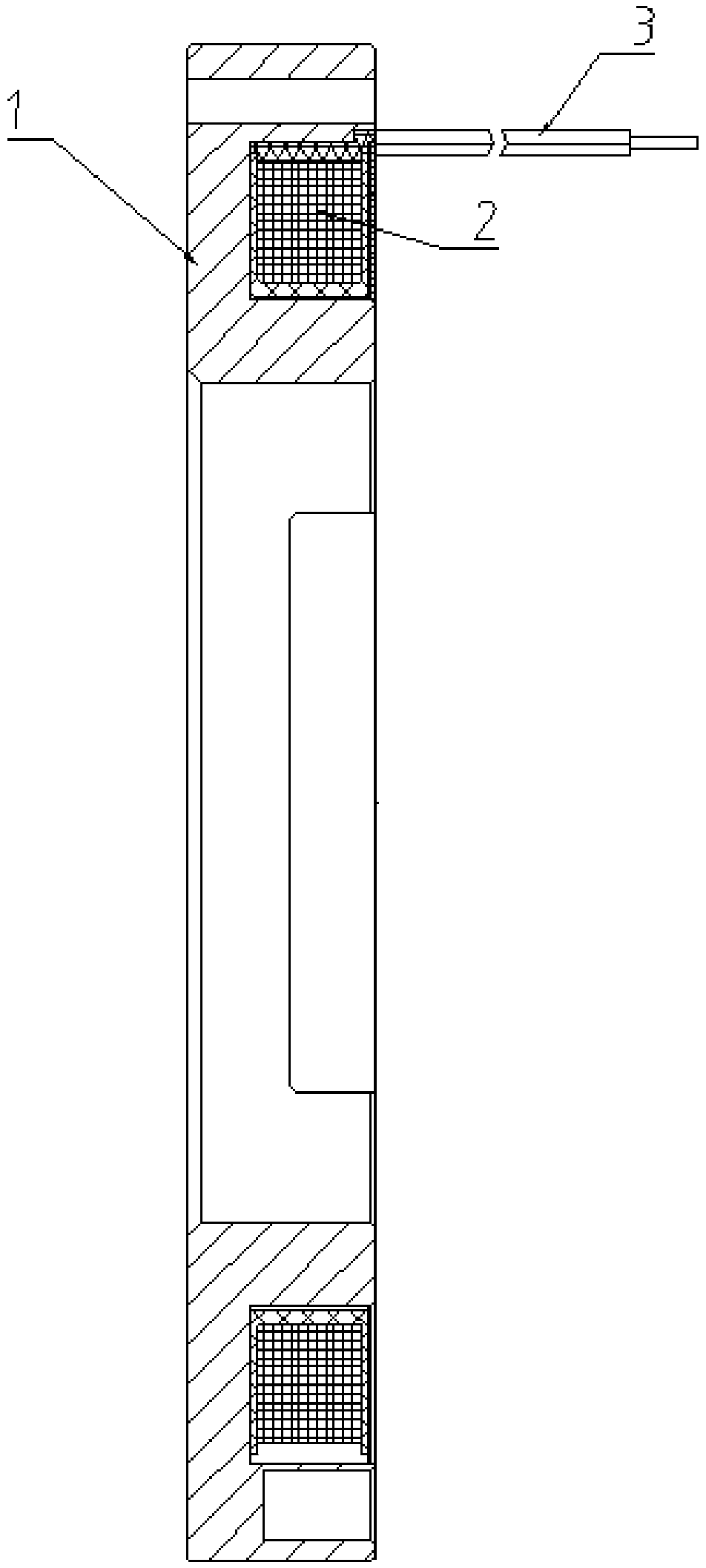
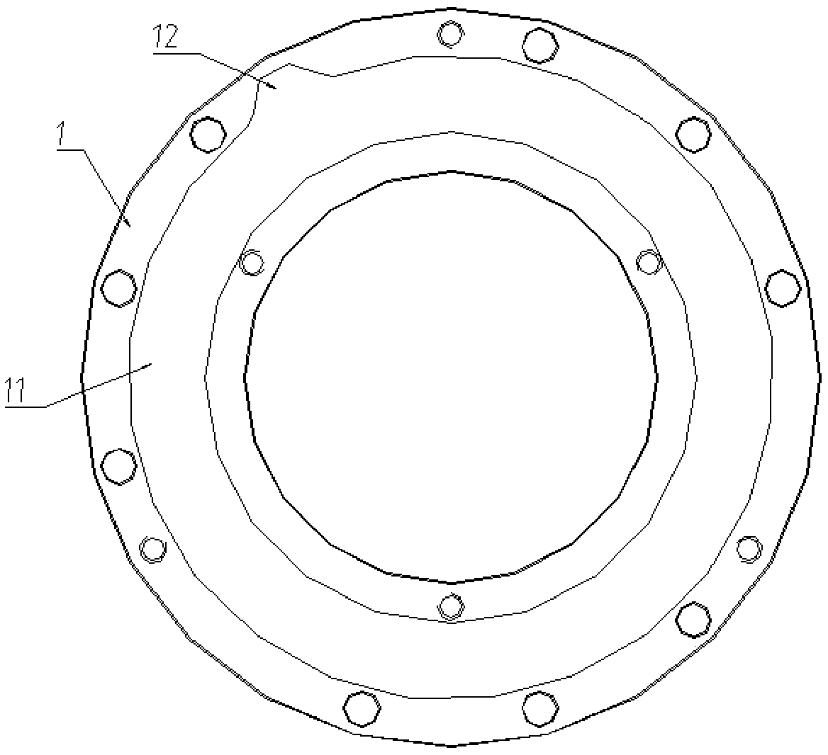
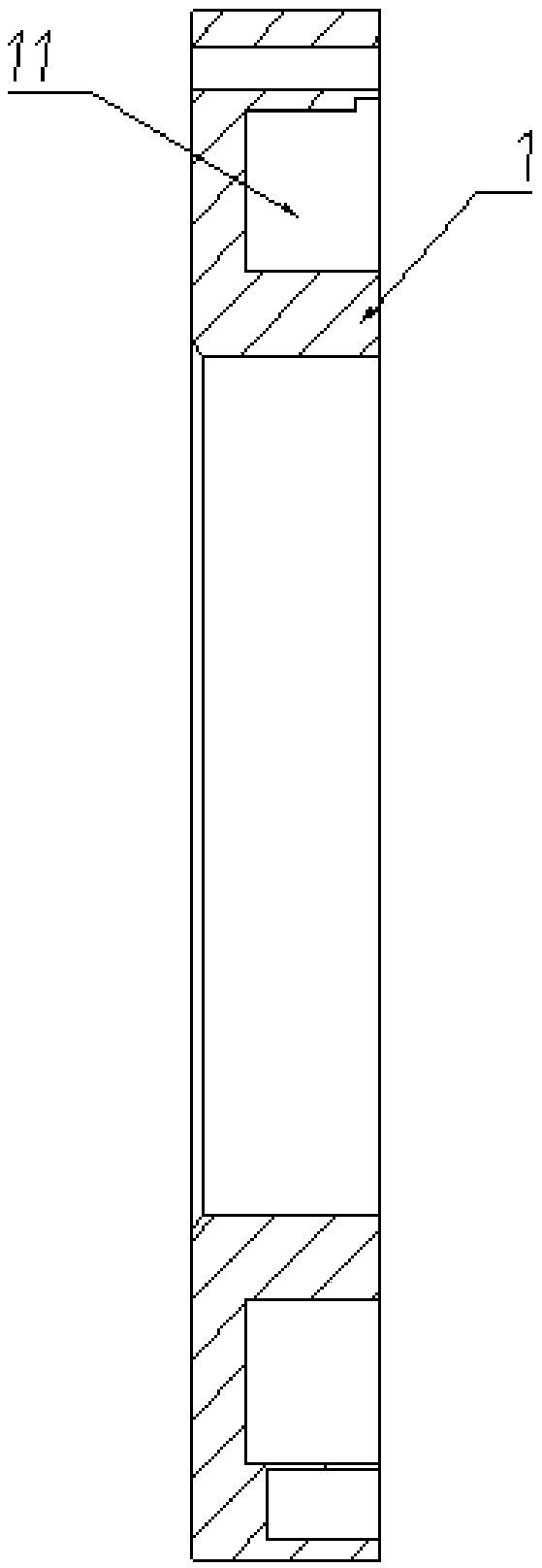
[0025] Such as Figure 1-5 As shown, a brake stator structure of a servo motor includes a stator core 1 and a stator 2 placed inside the stator core 1 . Specifically, the stator core 1 is a ring structure, and the stator core 1 is provided with a stator slot 11 for placing the stator 2, the stator slot 11 is an annular slot, and the stator slot 11 is along the ...


PUM


Abstract

The invention relates to a brake stator structure of a servo motor, comprising a stator core and a stator placed in the stator core. The stator iron core is of an annular structure, and a stator slotused for placing the stator is arranged on the stator core. The stator slot is an annular slot, and the stator slot is opened along one side of the axial direction of the stator core. The stator comprises a coil and a lead connected with the coil at one end, and an injection molding housing is formed on the outer surface of the stator through injection molding. In injection molding, the stator andat least one parts of the lead connected to one end of the stator are integrally formed through the injection molding housing. According to the stator structure, the stator and a part of the lead areintegrally formed, so that the lead can be effectively prevented from being disconnected from the stator during installation.

Description

technical field [0001] The invention relates to the field of servo motors, in particular to a brake stator structure of the servo motor and the servo motor. Background technique [0002] With the introduction of Industry 4.0, the demand for servo systems in more and more emerging fields such as robots is growing rapidly, and the opportunities are unlimited. The servo system includes a servo motor and a driver. The brake, the core component of the servo motor, has the functions of decelerating, stopping or keeping the moving parts in a stopped state, and its importance is self-evident. [0003] The outer ring of the existing brake stator only relies on the imide film to fix the coil, winding and lead wire welding, the effect is poor, and loose wires and flying wires will appear after a long time; when the stator and the iron core are installed, the stator cannot be connected with the stator iron core. The positioning of the lead wire trough often pulls the lead wire and the ...

Claims


Application Information

Patent Timeline
IPC IPC(8): H02K1/12H02K3/50
Inventor 王志强王周叶张雨婷谢艳丽
Owner GREE ELECTRIC APPLIANCES INC OF ZHUHAI
Why Eureka
Try Eureka